For 3b the best way to tab the signal is to connect direct to the sensor at the gearbox. If you connect other places you can have noise and you will get random values.
You can order the speed kit from vems.hu or make one yourself.
Happy Tuning
vems.dk
-
That sounds good then. Im planning to upgrade soon to those versions. So div by 9 is the best to try and recalcilate the timing with a strobe light?Leave a comment:
-
the flywheel has nothing to do with the wheelspeed.
wheel speed comes from the 3-pin (although it only actually has 2 pins in it) speed sensor on the side of the transmission. its VR type, and pics up a chunk of metal in a tone ring inside the transmission. Although to partially answer your question I've had good luck with 1.2.10 and 1.2.11 in general. Divby9 on the flywheel triggers seems to improve some issues some customers have with random engine speed trigger errors.Leave a comment:
-
Perhaps you should just give this to someone who is better versed in electronics and understands what inputs and outputs are - it will also minimize the chances of accidental damage to your engine control unit.
Sorry for trying to help, I will refrain from doing so in the future.Leave a comment:
-
You're arrogant on just about every forum you're on, aren't you? You did not describe what I need to do "to the letter."
"Box" aka transmission? What "box" are you referring to?The signal goes from the box to the speedo, the speedo buffers it, and then it goes from the speedo to other modules, such as the climate control, radio, cruise control and so on.
Meaning after the speedo. (cluster)?So what you want is splice the speedo output,
Meaning after the speedo. (cluster)?not the wire that comes from the gearbox.
This makes sense.And Marc has a point with the zener - you need to shunt the excess voltage so you do not damage the ADC on the processor.Leave a comment:
-
-
My apologize. that was engine speed.
Let me look into my AAN pin and will post up.
Motronic pin 50
3B = n/a
ABY= Vehicle Speed Signal
AAN= Instrument cluster (G21), Road Speed signal
G21 generate pulse signal, send to dash for speedo and multi+trip computor
Use this wheel speed input to EC18/8,
in my data sheet written "4k7 4k7 and 5v1 Zener protection diode"Last edited by kotnelson; 20 September 2013, 07:04.Leave a comment:
-
On a side note Marc, do you have any experience with the newer firmwares in regards to vems reading this signal clearer after 1.1.95? My problem is that although vems sees the wheelspeed sensor, if you remember it jumps around and its making vems very erratic. After sending files to vems.hu of trigger logs they said they cannot do anything. It seems that some Audi's the sensor reads clearly and in some it doesn't. (Even though in my car the flywheel pin is an excact replica of the dual mass flywheel now in size and width.)Leave a comment:
-
I have nothing to do with this vems stuff...
But AVR is also a popular label for the Microcontrollers from Atmel.
RegardsLeave a comment:
-
-
Yep, I'm certainty lost.
Looking at this diagram:
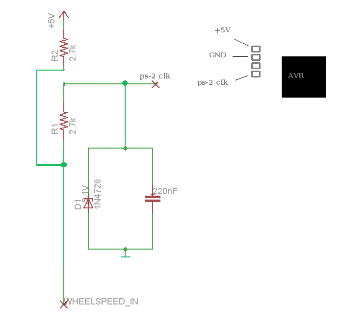
I am assuming AVR is the speedo sensor located in the transmission. Correct? If so, I don't want to be changing any wiring there that would render my factory speedo useless/incorrect. Not to mention, the factory sensor is only two pins, not 3...
This isn't a big deal, if I can't get it to work I am not loosing sleep over it. It looks as though even when implemented it's only "close". It'd be cool to play with gear dependent boost control, but again, it's not a necessity.Leave a comment:
-
Ok, I think you are confused here.
The signal goes from the box to the speedo, the speedo buffers it, and then it goes from the speedo to other modules, such as the climate control, radio, cruise control and so on.
So what you want is splice the speedo output, not the wire that comes from the gearbox.
And Marc has a point with the zener - you need to shunt the excess voltage so you do not damage the ADC on the processor.Leave a comment:
-
I don't want to loose the factory speedo either and looking at that diagram it seems as though it's re-wiring the factory sensor. The factory sensor also only uses two of the three pins.
Have you successfully wired the speedo into VEMS Marc? I have no problem assembling that little circuit, just want to make sure that's what I need to do.
I tapped into the speedo signal at the rear diff controller just to see what it was pulled up to. Stationary vehicle it's 10v. I spun the wheel by hand and it changed but didn't go over 10v. Could I assemble a voltage divider and input that?Leave a comment:


Leave a comment: