You can change the style the forum displays by selecting your preferred style at the bottom left of the site.
We have made an enhancement so that old threads should now link from search results to the correct thread. This is not yet in place for single post links
I tried the IAT calibration table above but it appears to be incorrect for my set up. After adjusting the calibration it read -2C when it was a 25C day and I'd been for a drive earlier. The previous calibration I have seems close though.
As for the ECT calibration, that seemed to work and matched the 'std bosch' calibration for the current static temp within 1C.
I tried the IAT calibration table above but it appears to be incorrect for my set up. After adjusting the calibration it read -2C when it was a 25C day and I'd been for a drive earlier. The previous calibration I have seems close though.
Sigh.
Not uncommonly, people ask for help but do not disclose all the details about their "set up" until those that try to help have wasted time going down the wrong path. We try to be helpful but believe it or not we are not all mindreaders like the amazing Kreskin. I now suspect that, in your case, you are running VEMS (or whatever) not Motronic. A little detail that would help you get your answer sooner.
If I remember correctly when going from Motronic to VEMS, for example, you need to use a NTC* IAT from a 1.8t because it has the required decreasing resistance with increasing air temp (as opposed to the stock AAN/ABY/ADU increasing resistance temp PTC** sensor). EFI Express mentions this obliquely in their website.
* In negative temperature coefficient (NTC) sensors, the internal resistance will decrease as the temperature rises (and vice versa).
** In a positive temperature coefficient (PTC) sensor, the opposite is true. Its resistance will increase with rising temperature.
If I am wrong and you are still running Motronic, I apologize. Still, full disclosure on your Motronic "set up" would be helpful.
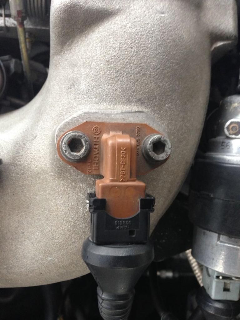
The clue was in the forum title: Aftermarket Engine Management. My ECU is a Link, as stated above in my third post (as edited a couple of minutes after posting). The ECU accepts input from all types of sensors. Not sure how this would effect the calibration table for the OE sensor. Resistance across the sensor terminals is proportional to temperature (either negatively or positively). There is a photo of the sensor in my first post. I don't know if it's OE or not which is why I posted a photo. If it is OE and your calibration graph is for the same sensor type then I would expect it to work with my Link ECU. All I need to do is tell it the starting temp value and increments and then fill in a table with the correct resistance for each temp step.
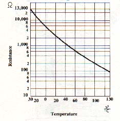
The calibration I'm using is PTC and it's similar to the plot above but shifted a little to one side. I know it's not 100% accurate but it's much better than the previous calibration the ECU was using which was for a NTC sensor. I was just hoping for something more accurate/definitive. I'll check it over again after I get back home from this work trip on Saturday to see if I made an error when I input the values from your graph.
Hint maybe but I honestly never see which sub-forum posts were posted in when I look at the list at the S2Forum, looking for threads that I might be able to help in, so I missed that. And I definitely missed this (hidden under the "Select Item" table image):
Edit to clarify: talking about PCLink software for Link ECU.
From your photo, if I blow it up and turn it sideways, I can see the PN on it as 034905379B. Asked my friend Kate, the friendly parts girl, about this PN, and she said that it is the OE AAN air temperature sensor so it is a PTC type and should follow that graph that I posted. It was used as early as a 1985 Audi 100 turbo and as late as the last UrS6 in 1997 (so MC, 3B, AAN, ABY, ADU, etc)
I would give you the stock calibration from the ECU, but unfortunately it is in voltage.
Meaning that there's a divider circuit using the sensor as one part of it and then it applies 5v to that, and linearizes based on voltage received at ADC after the divider.
It's possible to work it out, but need to measure all the resistors, since factory schematics do not include resistor nominals.
Ahem, so I had another go at using the IAT calibration curve kindly provided by UrS4boy as above. And, well it is working fine now Not sure what I did wrong last time. My sincere apologies to UrS4boy.
So the IAT graph above transferred to my calibration table looks like this:
We process personal data about users of our site, through the use of cookies and other technologies, to deliver our services, personalize advertising, and to analyze site activity. We may share certain information about our users with our advertising and analytics partners. For additional details, refer to our Privacy Policy.
By clicking "I AGREE" below, you agree to our Privacy Policy and our personal data processing and cookie practices as described therein. You also acknowledge that this forum may be hosted outside your country and you consent to the collection, storage, and processing of your data in the country where this forum is hosted.

 Tweet
Tweet


 Not sure what I did wrong last time. My sincere apologies to UrS4boy.


Comment