You can change the style the forum displays by selecting your preferred style at the bottom left of the site.
We have made an enhancement so that old threads should now link from search results to the correct thread. This is not yet in place for single post links
There are problems on the schematics alright... sometimes the wire colors are different.
The main mistakes of note are into the POS units - inputs 1 and 3 need to be swapped - I'll post up details on my schematics pages when I get time.
1 - I don't see the problem on this one - wrong colour wire ?
2 - Not sure you have captured the mistake properly - and its on BOTH POS units as described
3 - That sw/li wire you show at track 23 does route to 22 OK - look higher on the page for it.
Hi,
Let discribe the problems below:
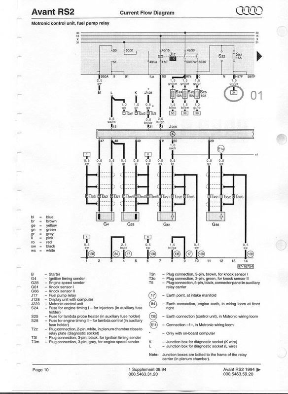
Problem 01: Fuel Pump - Page 10
First we have the Fuel Pump reley, and than go to the fuse, and there is a wire green and grey with 1,5mm that goes to the position 34!
At page 12, on position 34 we do not have anything, but the wire of the G6, the positive wire came from position 13, with the same colors of the wire indicated at page 10. So, I gess that we have a mistake there! It should be position 34 on my opinion.
Problem 02: G40 (Hall Sender)
The G40, at page 14, we have 3 wires on it. We have one that goes direct to the J220, on color green, a Earth conection at position 3 at the G40, with the wire color brown and yellow, that goes direct to the motronic wiring loom. And we should have the positive wire, with the colors red and black, that cames from the position 22.
At page 11, at position 22, que have a wire that conect position 22 with position 23. But the key point is that this positions are Earth. And something is wrong, because should be positive wire.
The colors are different too.
At the top of this page, we have another indicated position 22, that is the out-wire from the G62. The color is different too, and this 22 position is Earth conection too.
Problem 03: Ignition Coil
The ignition coil have 3 conection, first is the earth conection. The earth is its own housing. Than we have an positive conection, that cames from D14 and doesn´t mather the order at the conectors.
And we have the wire that came from the Output stage! This wire is the position 1 at the ignition coil.
So, at the ignition coil 4, the position 1 need to wire to the position 1 at the conector N127. and the ignition coil 5, must be conected to the position 2 at the conector N127.
The wire diagram have a mistake on this case!
Am I right?
Rafael Pinto
Audi S2 1994/1995 Avant - Black
Audi RS2 1994/1995 - Black
#1 is NOT a problem... Thats a green/yellow (gn/ge) wire that extends from the fuel pump relay thru the fuse and to the fuel pump (G6). Just imagine joining those to wires shown at track 13 and 34... Its just the extension of one wire - that's all those little square labels mean.
#2 is also NOT a problem - ignoring wire colour differences on some model years. Look carefully at track 22 - there is a red/black wire on the D3 signal which goes to track 64 as +ve input to G40.
#3 is getting warm... the POS and coil wiring has some mistakes alright. I need to dig out my notes on it - I don't want to post up bad info on this one...
PERFECT!!!! Now I understood what the square labels means!!!
But I am sure about the Ignition Coil! (Problem #3)
When I tried to start the engine of mine RS2, I have some problems withe the ignition order. Than I have analysed the conections of the Ignitions Coils from my S2-ABY and found that difference!
Thank you Paul!
Rafael Pinto
Audi S2 1994/1995 Avant - Black
Audi RS2 1994/1995 - Black
#3 is getting warm... the POS and coil wiring has some mistakes alright. I need to dig out my notes on it - I don't want to post up bad info on this one...
I don't know if this will help or not but I have previously identified that Bentley and others have the AAN POS diagram wrong. Here is what they say is correct (but they have the POS info wrong):
Think of that T4n connector (black 4-pin) as from ECU
Input 1 = Pin 4 (ro/sw) ..... This is wrongly labelled I3 on the sheet - tracks to ECU #20 for Cyl 04
Input 2 = Pin 3 (gn) ..... seems OK for ECU #21 which is Cyl 05
Input 3 = Pin 1 (not used on this POS of course)
GROUND at Pin 2 with br/ro wire
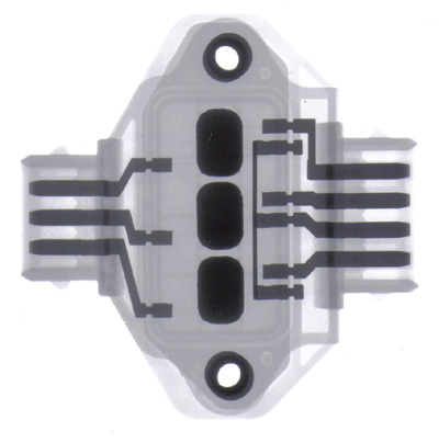
The 3-pin connector on the POS goes to the coilpacks. See UrS4 boys info with x-rays and other good stuff. The output pins T3ab/1 and 2 do not match the designated coil positions for Cyl04 and 05.
This gets confusing to describe... Needs a picture. I will try to draw up my own diagram of this and annotate as many documented wire colors across AAN, ABY and ADU thru the years.
So the channel number maps to the pin number on the 3-pin output connector at each POS
N122 covers cyl's 1-2-3
N127 covers cyls 4 & 5 - which is why we have the spare channel available at output pin 3 if you swap the input side for the spare channel to pin 1.
Just created a separate sticky with something I quickly drew up... I robbed that x-ray picture without asking permission but I hope thats OK. Figured it was public domain as such...
Just created a separate sticky with something I quickly drew up... I robbed that x-ray picture without asking permission but I hope thats OK. Figured it was public domain as such...
We process personal data about users of our site, through the use of cookies and other technologies, to deliver our services, personalize advertising, and to analyze site activity. We may share certain information about our users with our advertising and analytics partners. For additional details, refer to our Privacy Policy.
By clicking "I AGREE" below, you agree to our Privacy Policy and our personal data processing and cookie practices as described therein. You also acknowledge that this forum may be hosted outside your country and you consent to the collection, storage, and processing of your data in the country where this forum is hosted.






Comment