Removing Pins From the T55 ECU connector
All you had to do was ask and I would have posted this link:
Removing Pins From the T55 ECU connector:
-
Ah right you are, I couldnt work out how to dismantle the big plug, so that was a lucky guess!
Thanks for the help anyway!Leave a comment:
-
AAN Motronic ECU pin-out info
Just to be clear, there are three W/BL wires connected to the AAN ECU: at Pins 16, 22 and 50. However, if you look at the T55 pin numbering diagram, it should be easy to figure out which one is which and not mix them up.

16/55 - Output control signal to Fuel Injector No. 5 - N83 - W/BL
22/55 - Data Link Connector - W/BL - linked to Check engine light (Malfunction indicator lamp) - also used in the blink code check.
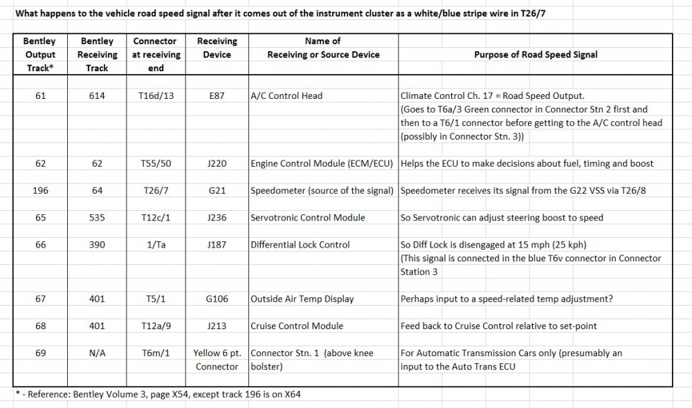
50/55- Road Speed signal input from the Instrument Cluster-G22-W/BL-signal - also goes to Automatic Climate Control Head Channel 17 - which you can read out speed as well, the Servotronic Control Module, the cruise control module and the UrS4 lockable rear differential controller (under the rear seat so it can dis-engage the rear diff lock at 15 mph (25 kph)). More details about the white/blue wire and where its branches go is available HERE. More info about the G22 Vehicle Speed Sensor (VSS) 012409191D . The ECU uses this road speed signal to know that the vehicle is moving so that when throttle position switch (Pin 52/55) is indicating closed but the vehicle is moving, the ECU can shut down the injectors to save fuel while coasting. Conversely, if the road speed is zero and throttle is closed, the ECU knows that this is the idle condition and it keeps the injectors active.
Branches of the G21 Road Speed output signal: http://forums.quattroworld.com/s4s6/msgs/238784.phtml
General AAN pin-out info: http://forums.quattroworld.com/s4s6/msgs/21009.phtml

Leave a comment:
-
For anyone interested in the solution to this, the thin wire from pin 50 white with blue trace (there are 2, it's the thinner of them, the other thicker one is for injector number 5) is the speed reading for ECU, which is the same colour used for the diff lock controller under the rear seats.
I cut the diff wire and moved it to ECU, but splicing would do the same job. If you cut it of course your diff won't automatically unlock (which is exactly what I wanted, 2 birds 1 stone)!
Apparently this info is not true of a 3b engine/loom as pin 50 is not used, you would have to fit said wire yourself.
And this was only to tell my launch control that I'm moving, it's not a necessary function
Leave a comment:
-
The info that I have posted reflects my understanding that Jolfa needed to hook up his speedometer.
And look at the that 3B G21/G22 diagram again. The white wire with the blue stripe that goes to the ECU and a bunch of other places, including the diff lock controller, leaves the 3B instrument cluster on Pin T26a/18.Leave a comment:
-
This doesn't make sense. G21 and G22 work together as a pair to produce the speed output signal that is used to drive the ECU input, diff lock, cruise control etc. and of course drive the actual speed display itself.
There is no situation where you'd want to connect anything to the wire link (br/red) between G21 and G22. If you do, you'll likely just stop G21 the speedo from working.
It's the white/blue VSS signal wire that needs to connect to the AAN ECU, if the speedo in a B3 80q generates a VSS signal, which I don't know.
JohnLast edited by johne; 18 April 2014, 23:44.Leave a comment:
-
Check the terminals in the speed sensor plug on the gearbox, they tend to get crusty
Leave a comment:
-
I had this same problem with my car. The cause in my case was the contact pins in the clocks. I soldered the two parts of the clocks together (the long pins that go throw the dial face). In my case the car suddently lost the signal and then found it again when I hit a speed pump or pothole.
Check the dials for possible cold joints also, I had few of these .
Leave a comment:
-
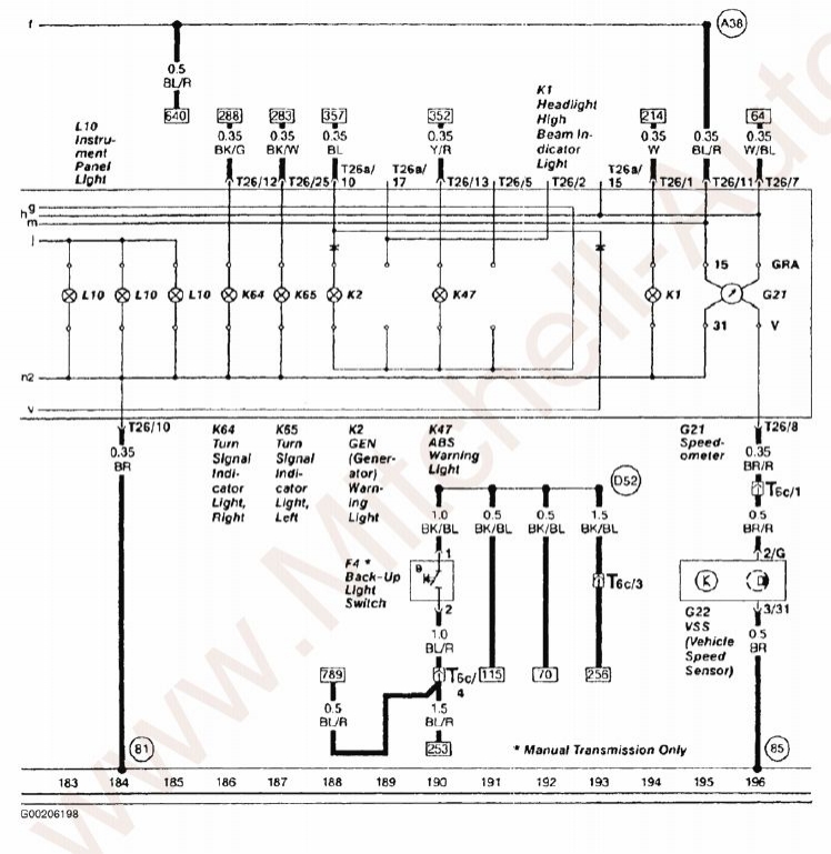
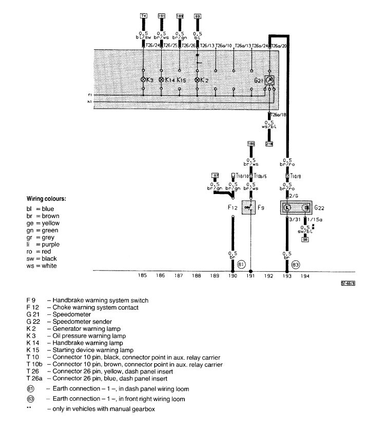
3B and AAN G22 Road Speed Sender to G21 Speedo wiring
New information has come to light. That and I got my head on straight. You are looking for the signal *TO* the G21 Speedometer *FROM* the G22 Road speed sender, NOT what comes out of the Speedometer. Try again. Looks like a brown wire with a red stripe is your "man" in both cases:
AAN G22 Road Speed Sender to G21 Speedometer wiring:
3B S2 G22 Road Speed Sender to G21 Speedometer wiring:
Leave a comment:
-
Well it should. Down load this from S2central.net:
Go to page 18/21. The Speedometer is device G21. The road speed signal generator is G22 (just like the C4 UrS4/S6 AANs). The wiring colours a different.Leave a comment:
-
AAN Road Speed Signal Connections
EDIT: The info in this post is potentially useful but the G22 VSS to G21 Speedo info you really need is in Post 4, below.
I was making some improvements to my diff lock post (i.e. pin-outs of the the diff lock controller). This led me to examine the G22 Vehicle Speed Sensor output. This led to finding and tracing the *SEVEN* potential) recipients of the road speed signal in a C4 UrS across the various pages in the Bentley electrical diagram. This is the result (might be useful in the future):
 Last edited by UrS4boy; 18 April 2014, 02:00.
Leave a comment:
-
80q/AAN road speed sensor?
I have an AAN converted B3 80q.
My ECU isn't getting a road speed signal and I'm reliably informed this is ECU pin 50 and needs a reading from my clocks.
Can anyone tell me if standard 2.0 8v clock wiring has this wire, and what colour wire it is on the ECU end and the clock end (I would assume the same colour but nothing is ever that easy!).
Also assuming the AAN loom has the wire I need, as the 3B loom doesn't apparently...
Thanks!



Leave a comment: