You can change the style the forum displays by selecting your preferred style at the bottom left of the site.
We have made an enhancement so that old threads should now link from search results to the correct thread. This is not yet in place for single post links
I know this has probably been discussed a thousand times over, but I just can figure out why my speedo won't work, I tried all the simple things like checking and spraying with contact spray the connection at the gearbox, plus the cluster connections, can someone tell me what colour wire on the blue cluster plug is the power/signal for the speedo?
It's a complete nest of wires down there
1991 S2 3B Coupe, KW v1, solid sub frames, poly bushed, chipped, about 260 ish
The Audi Enthusiast website. Forums for all Audis including A4, S4, A5, S5, A6, S6, allroad, A8, S8, TT, R8, Q5, Q7, 4000, 100, 200, v6, v8, vintage, local forums
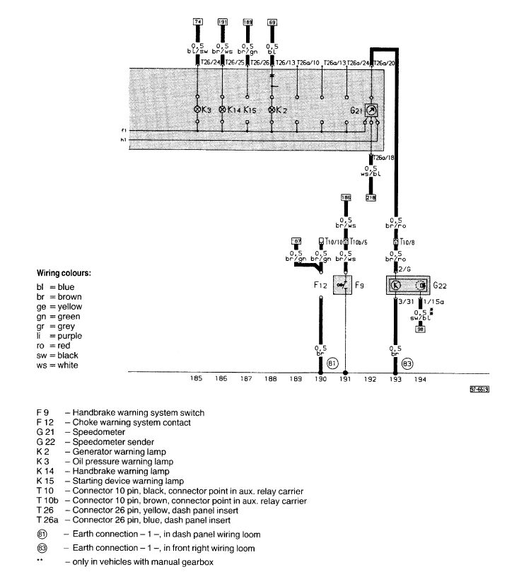
3B S2 G22 to G21 wiring diagram:
RS2'd 93 UrS4 5 spd sedan
94 UrS4 V8 6 spd manual avant
Not a huge help but the system is simple, consists of 4 things. BTDT
Speedometer/instrument panel - cold joints inside, but if you have tried 2 that should be ruled out. I have resoldered my numerous of times. The speedo needle was still jumping after a very long drive.
Changed magnetic ring on the drivers side inner cv axles flange, did not help
Changed sensor, that is over the mentioned flange, finally did help
And then there is wiring, but for some reason i do not believe it is faulty
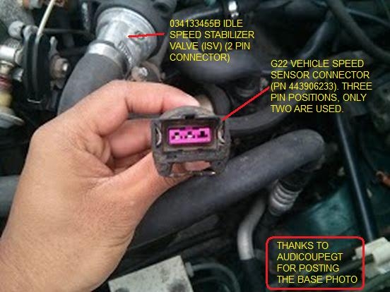
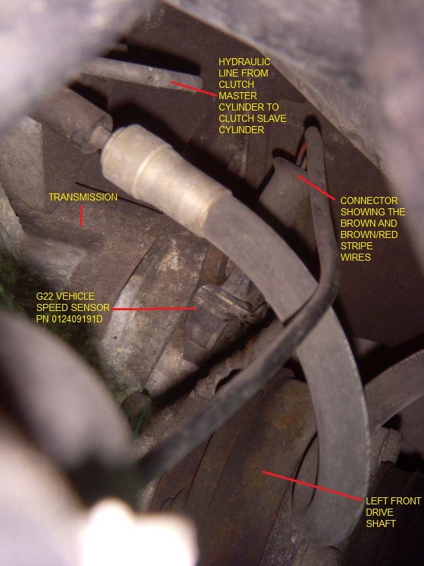
This happened locally to one of the Vancouver area UrS owners after he had the clutch replaced on his 94 UrS4. The shop failed to plug the G22 VSS connector cable back into the sensor.
RS2'd 93 UrS4 5 spd sedan
94 UrS4 V8 6 spd manual avant
Tested the sensor with a multimeter and some steel to replicate the relucter/exiter ring in box, sensor seems to be working, guess it's just down to me to figur out those diagrams, and locate that plug that speedinggg60 has shown in the pic in daves Quattroworld link. Which I can't find fit the life of me, kinda doing my head in now, thanks for everyone's help
1991 S2 3B Coupe, KW v1, solid sub frames, poly bushed, chipped, about 260 ish
Well, if you can't find the connector, you have the reason why your speedo isn't working. Nothing is connected to the G22.
sorry dave what i ment to say is i could not find the black t10 connector with the brow/red trace wire under the kickpanel, but a little break from the car and getting my head around that diagram you posted i think i have it sussed now, well so far i have continuity from the t10 plug to the cluster plug so thats ruled out!
just a matter of testing from the t10 back to the speed sensor now, job for tommorow!
ps: you dont happen to know if there is another connector between the black t10 connector and the vss, or is it a straight run wire?
thanks for all your help
1991 S2 3B Coupe, KW v1, solid sub frames, poly bushed, chipped, about 260 ish
just a matter of testing from the t10 back to the speed sensor now, job for tommorow!ps: you dont happen to know if there is another connector between the black t10 connector and the vss, or is it a straight run wire?
Based on that diagram that I posted, I would have said, straight run. However, based on this diagram (supposedly 3B), there is another connector, T8e (?) (Pin 7) along the Track 65 path between the G22 and the T10 connector:
Not sure where that first diagram came from but it's different to what I have for the 3B (as dave has now posted). I'd check you have a good earth to pin 3
I am not sure where I got the first one either.
So both the signal to the T10 and the ground are in the T8e connector, listed as being in the engine compartment, "right".
RS2'd 93 UrS4 5 spd sedan
94 UrS4 V8 6 spd manual avant
Thanks for the diagrams, as hard as it is for me to follow them
In this case it is relatively easy. Look at the bottom of the diagram for Track 65. Go up and find the G22 Vehicle Speed Sensor. The connector is a three pin. Pin 1 is empty. Pin 2 (in the middle) should have a red (rot) wire with a yellow (gelb) stripe. It is going to Pin 7 in an 8 pin T8e connector. Pin 3 in the G22 connector has a brown (braun) wire that goes to pin 6 in the same 8 pin T8e connector (it then goes to ground at (83) (in the front right wiring loom). Following the red/yellow wire up from the T8e (at pin 7) at some point it enters a T10 (ten pin) connector on pin 8. To confuse matters and do your head in, on the otherside of the T10 connector, this same line turns into a brown wire with a red (rot) stripe which then goes into the instrument cluster via the T26a (26 pin connector) on Pin 20. Once into the printed circuit board of the instrument cluster, it goes to the G21 speedometer.
RS2'd 93 UrS4 5 spd sedan
94 UrS4 V8 6 spd manual avant
We process personal data about users of our site, through the use of cookies and other technologies, to deliver our services, personalize advertising, and to analyze site activity. We may share certain information about our users with our advertising and analytics partners. For additional details, refer to our Privacy Policy.
By clicking "I AGREE" below, you agree to our Privacy Policy and our personal data processing and cookie practices as described therein. You also acknowledge that this forum may be hosted outside your country and you consent to the collection, storage, and processing of your data in the country where this forum is hosted.







Comment