

Ok guys need a little bit of help to explain this i was checking the s2 central pin out diagram and came across something strange the crimped earth leads that should be in pin 30 are in fact in pin 55 that's obd connector ,pin 30 ov ground should be black/pink is a thin green it does not connect to the crimped earth,s instead it disappears into a black conduit with a thin black wire .See photos i have used a multi meter probe to high light the thin green wire from pin 30
-
-
Not entirely sure what it is you that you need.
Are you sure you are counting the pins correctly? If the metal clamp is to the right and the top row is 19 pins then No1 is to the right and 19 is at the left. -
Common Device Grounds for the AAN ECU's T55/30 pin
Derek: Not exactly what you are looking for but the parallels for the ABY will be there (but with different wire colours:
******************
AAN Common Grounds:
7 wires enter the common crimp located inside the T55 ECU connector. 5 of these wires are Green/Black, one is yellow and one is brown. The G42 IAT is one of the green/black wires.
A single green/black wire exits the common crimp and runs to the T55/30 pin.
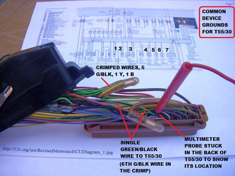
T55 ECU connector pin map, from the front:

The seven devices are, left to right,
1. G61 knock sensor, 2. G66 knock sensor, 3. Idle switch/throttle potentiometer, 4. F96 Altitude sensor, 5. G62 engine coolant temp sensor, 6. G42 Intake air temp sensor and 7. Coding card for trip computer (probably regardless of whether the trip computer is installed or not).
 RS2'd 93 UrS4 5 spd sedan
94 UrS4 V8 6 spd manual avantComment
-
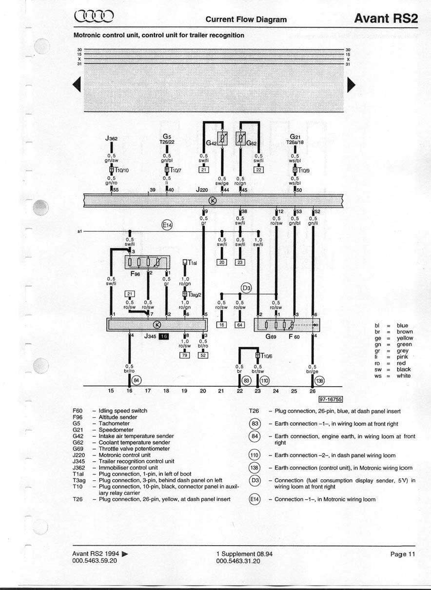
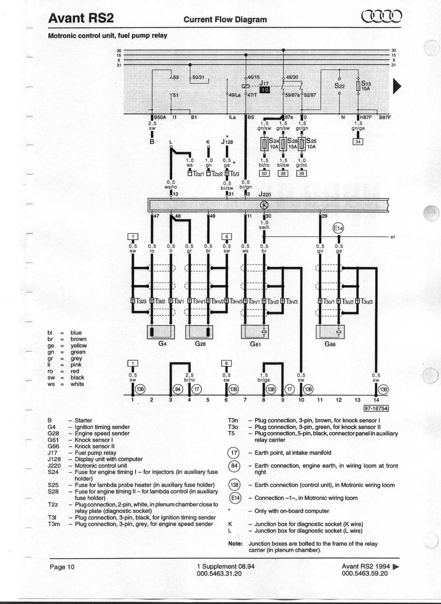
Derek: Here is the other trace from the G62 to Pin T55/30 in a 3B ECU:
Note the G62 and a few others trail together as "a1" ([31] to [27] to "a1")

Here is the "a1" link on its way to the T55/30
 RS2'd 93 UrS4 5 spd sedan
94 UrS4 V8 6 spd manual avantComment
-
Just to update and confirm: These G62-related ADU ECU diagrams are from S2Central.net. Look the same wire colour-wise as the 3B diagrams so the inference is the ABY diagrams would be the same.
Red/green to Pin T55/45
Black/violet Track [23] to Track [22] and then to "a1" and on to Pin T55/30 in the second diagram.
 RS2'd 93 UrS4 5 spd sedan
94 UrS4 V8 6 spd manual avantComment


Comment