Engine Temperature Fluctuation and High CO Levels on Audi 80 2.8 V6 AAH (1993)

Collapse
X
 
  • Time
  • Show
Clear All
new posts
  • PetterHolmqvist
    S2Forum Tinkerer
    • Dec 2025
    • 1
    • Country: Sweden

    #1

    Engine Temperature Fluctuation and High CO Levels on Audi 80 2.8 V6 AAH (1993)


    I have an Audi 80 2.8 V6 AAH from 1993. I’ve replaced the timing belt and at the same time replaced a worn water pump and thermostat. The thermostat was probably bad before, since the engine never reached 90°C on the gauge and the thermostat never opened.

    Now the engine warms up slowly and sometimes reaches 90, but then drops back down to around 70 or even lower. I’ve unplugged the temperature sender for the gauge and measured the resistance — it seems correct. I also shorted the connector, and then the temperature gauge goes up to 120°C, so the gauge itself should be working.

    I measured the CO levels during inspection and they are too high. What is the problem? Could it be a bad coolant temperature sensor telling the ECU that the engine is too cold and therefore injecting more fuel? Could it be a damaged gasket or a vacuum leak?

    When I sprayed brake cleaner on the driver’s side the engine speed dropped for a moment — suspected leak in the intake manifold gasket or injector seals. The thermostat works (tested in boiling water) and I can feel that the radiator hoses get warm even when the gauge shows ~70°C. The exhaust is very white, but the car has been sitting for a long time so I’m assuming old fuel. The coolant doesn’t smell like exhaust gases, the levels seem fine, and I don’t suspect a head gasket issue. Oil and coolant are clean.

    Could there be air in the cooling system causing the temperature sensor not to make contact with coolant and therefore read too low? I’ve checked for fault codes with OBD but it shows nothing and no live data since it’s an old car. There should also be a small screw by the MAF sensor to adjust the CO levels if I’m not mistaken, but I don’t want to mess with it, and it feels like the temperature issue is the real culprit.

    I’m not an expert and I’m just speculating, but feel free to give suggestions and correct me if I’m wrong.
  • Lago Blue
    S2Forum Maniac
    • Jul 2009
    • 843
    • Country: Canada

    #2
    Hi Petter,

    I think you are doing pretty good.

    Q: What is the problem?
    A: It could be more than one thing.

    Q: Could it be a bad coolant temperature sensor telling the ECU that the engine is too cold and therefore injecting more fuel?
    A: Possibly, see G62 procedure at link:


    Re: "The exhaust is very white, but the car has been sitting for a long time"
    Response: It may be that the injectors are not shutting off completely, if so they could be sent out for cleaning.

    Q: Could it be a damaged gasket or a vacuum leak?
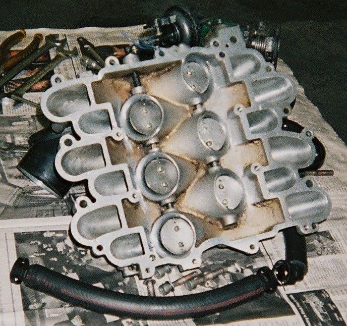
    A: This (the entire vacuum system) could be part of the engine performance issue. There are many I/M interfaces (see drwg. at link) which could all leak on a 2.8 North American all-metal manifold.

    Perhaps yours does not have an EGR? Is yours in part made of plastic? Does it have the long / short passage change-over butter-fly plates?


    Fixing all the possibles here is entirely do-able, see #14 Intake Manifold ... for more info here:

    12v V6 Discussion - Tour (II) Through a Modest (& Mostly OEM) Intake System; Intro... - https://cimg9.ibsrv.net/gimg/www.audiworld.com-vbulletin/688x646/picture_php_pictureid_193596_432a61afe932010c5fa29c760f073ee5c9e2acaa.jpg tubular_bells.jpg ...the effective (w)hole is greater than the $um of its' parts. Intro &...


    Q: Could there be air in the cooling system causing the temperature sensor not to make contact with coolant and therefore read too low?
    A: Perhaps, do you have a bleed screw by the G62 (see drwg. at link below), getting all the air out is usually tedious. The heater hose elbow bleed screw is a pretty delicate arrangement. Often neglected during coolant change-outs is the engine block drain and passage. I've read that accumulated debris here may become dislodged and can cause recurring issues elsewhere (t-stat, rad and heater blockage).


    Re: "...no live data since it’s an old car".
    Response: Some cars had the GM built electronic climate control and I read there is a way to make it display engine coolant temp.

    Re: "MAF sensor" screw.
    Response: I agree. It may be that both F76 and G62 are old and tired. Perhaps a laser temp gun would be helpful to confirm temps?


    Comment

    • Ryan80
      S2Forum Enthusiast
      • Jan 2008
      • 154
      • Home: Northern Ireland Current: United Kingdom

      #3
      Further to Lago Blue excellent response, a simple question that can help with the troubleshooting - Do the internal blowers blow warm air when set to heat? if they dont it would confirm air in the system, especially at the heater matrix since its one of the highest points of the system.

      The 12v.org pages are wealth of knowledge for these much unloved engines, well worth a read through
      Time waits for no man. Unless that man is Chuck Norris.

      Comment

      • Crasher
        S2Forum Enthusiast
        • Nov 2018
        • 139
        • Country: England

        #4
        An OBD code reader is useless on this ECU, VCDS would be ideal and you could use the basic version but this won't allow output tests or basic settings which are essential in the setup; I assume you have a 2x2 to 16 pin adapter? Is the ECU part number 8A0 906 266 B? There is no CO adjustment on the AAH with a Lambda sensor. There are 19 measuring blocks display groups with very useful data. When I was regularly working on these in the 90's, I found they were very fussy about cam timing and unless the belt was fitted with the crank and cams locked,using the crank pin and cam to cam locking bar, also with the pulleys freewheeling on the tapers, they would run poorly.
        Reading measured value block: Display groups 000 to 010
        Read measured value block 0 ⇒ ◂ Indicated on display
        1 2 3 4 5 6 7 8 9 10 ◂ Display zones Specification Corresponds to
        Learned value for throttle valve potentiometer 50...100 250...500 mV
        Lambda learning demand
        0 = Learning demand at idling speed and part throttle range
        3 = Learning process completed at idling speed
        3
        Lambda control value (mean value 128/cyl. 1...3)
        0 is displayed for vehicles with no lambda probes
        120...136
        Switching inputs ...
        Idling stabilisation feedback (mean value 128) 126...130
        Learned value for idling stabilisation, automatic gearbox with gear engaged (0 is displayed for manual gearbox) 0...10 or
        236...255
        Learned value for idling stabilisation, manual gearbox in idling position, automatic gearbox in selector lever position P or N 0...14 or
        240...255
        Engine speed 28...32 700...800 rpm
        Air mass meter output voltage 147...162 1,47...1,62 V
        Coolant temperature 135...160 85...110 °C
        Notes on Display Group 000:
        • ◆ If the values displayed do not correspond to the specified values, use the following display groups 001 - 019 for fault rectification.
        • ◆ Do not deal with any deviations in display zone 8 until the lambda learning process at idling speed has been completed => display zone 9.
        • ◆ If values greater than 3 are displayed in display zone 9 => Display group 007 or 008.
        Display Group 001; basic function
        Reading measured value block 1 ⇒ ◂ Indicated on display
        ... °C ... V ... V ... V
        Engine control unit voltage supply
        ▪ 12,0 ... 14.0 V OK
        Air mass meter discrepancy
        ▪ 0,000 ... 0.025 V
        Air mass meter output voltage
        ▪ 1,470 ... 1.620 V OK (for new engines, max. 1.680 V)
        ▪ In the event of engine speed increase, display value rises to 2.500 V, drops to 0.000 V and starts rising again.
        Coolant temperature
        ▪ 85 ... 110 °C ok
        Test table, Display group 001
        Display zone Readout on V.A.G 1551 Cause of fault Fault remedy
        1 Less than - Engine too cold - Perform test drive if necessary
        85 °C 1) - Coolant temperature sender or wiring to engine control unit - Interrogate fault memory
        Greater than - Radiator dirty - Clean radiator
        110 °C 1) - Radiator fan not working - check function
        - Thermostat defective - Checking coolant thermostat
        - Coolant temperature sender or wiring to engine control unit - Interrogate fault memory
        1) Vehicle at operating temperature.

        Note on display zone 1:

        The coolant temperature sender is a temperature-sensitive resistor. If the sender signal is biased, for example due to moisture in a connector (effect similar to parallel resistor), this biasing may be in a range which the fault memory is still not able to detect.
        Display zone Readout on V.A.G 1551 Cause of fault Fault remedy
        2 Less than
        1,470 V
        - Large quantity of unmetered air between intake manifold and air mass meter - Eliminate unmetered air
        Greater than
        1,620 V
        - Loads switched on, e.g. air conditioner is on; steering wheel is at end stop; selector lever of automatic gearbox not set to position "P" or "N" - Switch off all electrical loads
        Centre steering wheel
        Move selector lever to "P" or "N"
        Notes on display zone 2:
        • ◆ Only assess the tolerance range of the air mass meter output voltage in function 04 "Basic setting" at idling speed.
        • ◆ The air-mass meter output voltage decreases by 0,01 V for every 500 m above sea level.
        • ◆ If the above-mentioned fault causes are not applicable, subtract the value in display zone 3 (air mass meter discrepancy) from the increased value in display zone 2. If the result lies within the tolerance range, the increased value in display zone 2 is no longer valid.
        Display zone Readout on V.A.G 1551 Cause of fault Fault remedy
        3 Greater than 0.025 V - Defective wiring or contacts or oxidised earthing point - Check earth supply for air mass meter -G70
        4 Less than 12,0 V - Alternator defective, battery heavily discharged - Checking voltage, charge battery
        - High load on electrical system shortly after starting engine due to high charge current and load from ancillaries - Increase engine speed for several minutes and switch off ancillaries
        - Contact resistance in power supply or earth connection for engine control unit - Check voltage supply to engine control unit
        - Current drain with ignition off - Eliminate current drain
        Greater than 14,0 V - Voltage control on alternator defective - Checking voltage; if necessary, replace the voltage regulator.
        - Excess voltage from assisted start or high speed charger - Interrogating fault memory
        =>Page 01-11
        Note on display zone 3:

        If fault "00531 air mass meter reference voltage" is stored, a substitute value of constant 0.02 V is displayed.

        Display group 002, throttle valve potentiometer:
        Reading measured value block 2 ⇒ ◂ Indicated on display
        ... V ... V ... V 0
        Idling switch
        ▪ 0 = open
        ▪ 1 = closed
        Learned value for throttle valve potentiometer
        ▪ 0,250 ... 0.500 V OK
        Throttle valve potentiometer voltage (idling speed to part throttle range)
        ▪ 0.250 ... 1.275 V OK
        Throttle valve potentiometer voltage (idling speed to full throttle range)
        ▪ 0.250 ... 4.750 V OK
        Test table, Display group 002
        Display zone Readout on V.A.G 1551 Cause of fault Fault remedy
        1 Deviation from tolerance range - Throttle valve potentiometer -G69 defective or incorrectly set - Interrogate fault memory or => Display group 009, display zone 4
        2 Outside
        the tolerance range
        - Throttle valve potentiometer -G69 defective or incorrectly set - Interrogate fault memory or => Display group 009, display zone 4
        3 Outside
        the tolerance range
        - Idling switch actuated or defective
        - Throttle valve potentiometer -G69 defective or incorrectly set
        - Interrogate fault memory or => Display group 009, display zone 4
        - Loads switched on, e.g. air conditioner is on; steering wheel is at end stop; selector lever of automatic gearbox not set to position "P" or "N" - Switch off all electrical loads
        Centre steering wheel
        Move selector lever to "P" or "N"
        - Moisture in connector of throttle valve potentiometer -G69 - Checking connector
        - Earth point at intake manifold - Checking earth connection
        => "Current Flow Diagrams, Electrical Fault Finding and Fitting Locations" binder
        Notes on display zone 3:
        • ◆ Idling switch must be closed for checking throttle valve potentiometer learned value => Display zone 4.
        • ◆ If the displays in zones 2 and 3 agree at idling speed, the learning process is OK. The last value learned is constantly displayed if no learning process takes place.
        • ◆ The throttle valve potentiometer learned value is set to 0.550 V if the control unit is de-energised.
        Display zone Readout on V.A.G 1551 Cause of fault Fault remedy
        4 0 or 1 - -F60 idling switch defective
        - Throttle valve potentiometer -G69 defective or incorrectly set
        - Interrogate fault memory
        - Throttle valve sticking
        - Floor mat pressing down on accelerator pedal
        - => Display group 011, Display zone 4
        Eliminate cause
        - Moisture in connector of throttle valve potentiometer -G69 - Checking connector
        - Throttle cable setting - Adjust throttle cable
        Display Group 003; basic function
        Reading measured value block 3 ⇒ ◂ Indicated on display
        ...rpm ... % ... % ... km/h
        Vehicle speed
        Throttle valve angle:
        ▪ Idling: 0 % OK
        ▪ Full throttle: Greater than 95 % OK
        Engine load (idling speed)
        ▪ 15,0 ... 32.0 % OK
        Engine speed (idling speed)
        ▪ 700 ... 800 rpm OK
        Test table, Display group 003
        Display zone Readout on V.A.G 1551 Cause of fault Fault remedy
        1 Greater than 800 rpm - Idling switch -F60 incorrectly set or defective - Check and adjust idling speed switch -F60
        or => Display group 004, Display zone 4
        - Idling stabilisation valve -N71 is sticking or stiff - Perform final control diagnosis .
        - Air intake system drawing in large quantities of unmetered air - Checking air intake system for leaks
        Less than 700 rpm - Idling stabilisation valve -N71 is sticking or stiff - Perform final control diagnosis
        - Idling switch -F60 incorrectly set or defective - Checking and adjusting idling speed switch -F60
        or Display group 004, Display zone 4
        - Loads switched on, e.g. air conditioner is on; steering wheel is at end stop; selector lever of automatic gearbox not set to position "P" or "N" - Switch off all electrical loads
        Centre steering wheel
        Move selector lever to "P" or "N"
        Display zone Readout on V.A.G 1551 Cause of fault Fault remedy
        2 Outside
        the tolerance range
        - Poor idling (not running on all cylinders) - Injector or spark plugs defective
        - Air mass meter -G70 defective - Interrogate fault memory or => Display group 001, Display zone 2
        - Idling stabilisation valve -N71 defective - Interrogate fault memory or =>Display group 018
        - Loads switched on, e.g. air conditioner is on; steering wheel is at end stop; selector lever of automatic gearbox not set to position "P" or "N" - Switch off all electrical loads
        Centre steering wheel
        Move selector lever to "P" or "N"
        - Exhaust gas recirculation valve -N18 leaking - Interrogate fault memory or Display group 017
        Note on display zone 2:

        Only assess engine load tolerance range at idling speed in function 04 "Basic setting"
        Display zone Readout on V.A.G 1551 Cause of fault Fault remedy
        3 Greater than 0 % at idling speed - -G69 throttle valve potentiometer defective - Interrogate fault memory or =>Display group 002
        - Throttle cable setting - Adjust throttle cable
        - Throttle valve sticking - Eliminate cause
        Less than 95 % at full throttle - -G69 throttle valve potentiometer defective - Interrogate fault memory Display group 002
        - Throttle cable setting - Adjust throttle cable
        - Throttle valve potentiometer -G69 incorrectly set - Checking throttle valve potentiometer -G69
        Note on display zone 3:

        For checking at full throttle, switch engine off and ignition on.
        Display zone Readout on V.A.G 1551 Cause of fault Fault remedy
        4 No
        Display
        - Fault in wiring between dash panel insert and engine control unit - Check wiring
        - Open circuit or short circuit between vehicle speed sender -G22/-G68 and engine control unit - Check wiring
        - Vehicle speed sender -G22/-G68 - Check vehicle speed sender
        Note on display zone 4:

        If vehicle speed is not displayed on V.A.G 1551, start by checking whether speedometer reading is OK. If not, check speedometer:

        Display group 004: Idling speed stabilisation:
        Reading measured value block 4 ◂ Indicated on display
        1 4 0 0 0 1 1
        X X X X ▪ Fresh-air blower for air conditioner: 0 = high, 1 = low
        ▪ Air conditioner compressor: 0 = off, 1 = on
        ▪ Idling switch: 0 = open, 1 = closed
        ▪ Gear recognition signal: 1 = manual gearbox or automatic gearbox in selector lever position "P" or "N"
        ▪ 0 = automatic gearbox in selector lever position R, D, 3, 2, 1
        Idling stabilisation learned value for automatic gearbox (AT)
        ▪ In selector lever position D, 3, 2, 1 or R +10 ... -20 OK
        ▪ Display always 0 for manual gearbox (MT)
        Learned value for idling stabilisation
        ▪ For manual gearbox (MT) in idling position +14 ... -16 OK
        ▪ (new engines +20 ... -16)
        ▪ For automatic gearbox (AT) in selector lever position "P" or "N" +10 ... -20 OK
        ▪ (new engines +16 ... -20)
        Idling control at idle
        ▪ 0 ± 2 OK
        Notes on display zones 2 and 3:
        • ◆ Only assess values in display zone 2 or 3 if idling control is within tolerance at idle (display zone 1). If idling control is not within the tolerance after 1 minute waiting time, learning does not take place in display zone 2 or 3.
        • ◆ Positive learned values indicate higher learned value than in basic setting: -N71 further open.
          Negative learned values indicate lower learned value than in basic setting: -N71 is further closed.
        Test table, Display group 004
        Display zone Readout on V.A.G 1551 Cause of fault Fault remedy
        1 Outside the - Fault in fault memory - Interrogate fault memory
        tolerance
        range
        - Idling switch -F60 actuated or defective - Check idling switch -F60 and Display group 002, display zone 4
        - Idling stabilisation valve -N71 defective - Check idling stabilisation valve -N71
        - Loads switched on, e.g. air conditioner is on; steering wheel is at end stop; selector lever of automatic gearbox not set to position "P" or "N" - Switch off all electrical loads
        Centre steering wheel
        Move selector lever to "P" or "N"
        - Throttle valve sticking
        - Floor mat pressing down on accelerator pedal
        - Unmetered air
        - Eliminate cause
        Display zone Readout on V.A.G 1551 Cause of fault Fault remedy
        2 Greater than +14 (MT) - Idling stabilisation valve -N71 defective - Check idling stabilisation valve -N71
        or
        Greater than +10 (AT)
        - Loads switched on, e.g. air conditioner is on; steering wheel is at end stop; selector lever of automatic gearbox not set to position "P" or "N" - Switch off all electrical loads
        Centre steering wheel
        Move selector lever to "P" or "N"
        - Suction jet pump clogged (automatic gearbox) - Eliminate cause
        - EGR valve -N18 open - Interrogate fault memory or Display group 017
        Less than -16 (MT) - Idling stabilisation valve -N71 defective - Interrogate fault memory or =>Display group 018
        or
        Less than -20
        (AT)
        - Large volume of unmetered air, intake manifold area, throttle valve stop not OK, leakage air at throttle valve 2nd stage - Eliminate cause
        Display zone Readout on V.A.G 1551 Cause of fault Fault remedy
        3 Outside the
        tolerance
        Vehicles with automatic gearbox only:
        range - Display zone 2 outside tolerance range Display zone 2
        - Display zone 2 within tolerance range
        - Set selector lever to D and observe idling speed for approx. 1 min; if display zone 3 remains outside tolerance range, then the gearbox will not operate smoothly - Checking gearbox
        4 Not
        001 1
        - Idling switch -F60 actuated or defective - Check and adjust idling speed switch -F60
        - A/C compressor switched on - Switch off the air conditioner
        - Air conditioner requires higher cooling or heat output ("high") - Check air conditioner compressor shut-off
        - Gear engaged (automatic gearbox) - Move selector lever to P or N
        Display group 005, lambda learned values, cylinder bank 1:
        Reading measured value block 5 ⇒ ◂ Indicated on display
        ... % ... % ... % ... %
        Lambda learned value, part throttle 3 (bank 1)
        ▪ -19 % ... +19 % OK
        Lambda learned value, part throttle 2 (bank 1)
        ▪ -19 % ... +19 % OK
        Lambda learned value, part throttle 1 (bank 1)
        ▪ -19 % ... +19 % OK
        Lambda learned value, idling speed (bank 1)
        ▪ -25 % ... +25 % OK
        Notes on all display zones=> Display group 006

        Display group 006, lambda learned values, cylinder bank 2:
        Reading measured value block 6 ⇒ ◂ Indicated on display
        ... % ... % ... % ... %
        Lambda learned value, part throttle 3 (bank 2)
        ▪ -19 % ... +19 % OK
        Lambda learned value, part throttle 2 (bank 2)
        ▪ -19 % ... +19 % OK
        Lambda learned value, part throttle 1 (bank 2)
        ▪ -19 % ... +19 % OK
        Lambda learned value, idling speed (bank 2)
        ▪ -25 % ... +25 % OK
        Notes on all display zones:
        • ◆ Positive learned value (+ %) signifies:
          Mixture too lean, more fuel must be injected (programmed basic injection period too short, actual injection period ... % longer, so that λ = 1 is achieved)
        • ◆ Negative learned value (+ %) signifies:
          Mixture too rich, less fuel must be injected (programmed basic injection period too long, actual injection period ... % shorter, so that λ = 1 is achieved)

        Test table: Display groups 005 and 006

        Display zone Readout on V.A.G 1551 Cause of fault Fault remedy
        1/2/3/4 Low lambda
        learned values
        If learned value in display zone 1 is low and the learned values in display zones 2, 3 and 4 are normal:
        - Oil dilution (high petrol content in oil) - Disconnect and seal off crankcase breather
        Problem eliminated after motorway drive or oil change
        - Injector leaking - Check injection valves
        If all 4 lambda learned values are very low:
        - Fuel pressure too high - Check fuel pressure 8
        - Solenoid valve 1 for activated charcoal filter -N80 is constantly open - Check -N80 or Display group 009, display zone 3
        - Air mass meter -G70 defective - Check -G70 5
        (cont.)
        t
        - Lambda probe heating defective or lambda probe dirty - Check lambda probe or =>Display group 010, display zones 1 and 2
        Display zone Readout on V.A.G 1551 Cause of fault Fault remedy
        1/2/3/4 High lambda
        learned values
        If learned value in display zone 1 is high and the learned values in display zones 2, 3 and 4 are normal:
        - Unmetered air in intake manifold area - Eliminate causes
        - Injector clogged - Test injection quantity
        If all 4 lambda learned values are very high:
        - Air mass meter -G70 defective - Check -G70
        - Fuel pressure too low - Checking fuel pressure
        - Unmetered air between -G70 and throttle valve
        - Unmetered air at manifold gasket
        - Eliminate cause
        - Lambda probe heating defective or lambda probe dirty - Checking lambda probeor =>Display group 010, display zones 1 and 2
        Notes on display groups 005 and 006:
        • ◆ Differences in lambda learned values (=> Display group 010, display zones 1 and 2 ) of more than 8 % between display group 005 (bank 1) and display group 006 (bank 2) may be due to the following:
          - Defective spark plugs
          - Defective injectors (leaking, clogged)
          - Unmetered air at one end
          - Lambda probe defective or dirty
          - Mechanical base setting (valve timing) of engine not OK
        • ◆ If the difference between the richest and leanest lambda learned value of a display group is 9 %, any further leaning of the two learning ranges in question is stopped (=> Display group 007 or 008). The learning demand display (=> Display group 007 or 008) for these learning ranges cannot be 1.
        • ◆ All values are reset to 0.0 % if control unit is deenergised.
        Display group 007, lambda control, cylinder bank 1:
        Reading measured value block 7 ⇒ ◂ Indicated on display
        ... % ... % X X X X XXXXXXXX
        Lambda learning demand display (bank 1)
        X X

        X


        X
        Lambda learning range display (bank 1)
        ▪ Part throttle 3:0 = engine speed and load for this learning range not attained
        ▪ 1 = engine speed and load for this learning range attained
        ▪ Part throttle 2:0 = engine speed and load for this learning range not attained
        ▪ 1 = engine speed and load for this learning range attained
        ▪ Part throttle 1:0 = engine speed and load for this learning range not attained
        ▪ 1 = engine speed and load for this learning range attained
        ▪ Idling speed:0 = engine speed for this learning range not attained
        ▪ 1 = engine speed for this learning range attained
        Instantaneous lambda learned value (bank 1)
        Lambda control (bank 1)
        ▪ 0,0 ± 6.0 % OK 1)
        1) Only assess the lambda control tolerance range at idling speed in function 04 "Basic setting", as function 08 "Reading measured value block" also includes control of ACF influence.

        Display group 008, lambda control, cylinder bank 2:
        Reading measured value block 8 ⇒ ◂ Indicated on display
        ... % ... % X X X X XXXXXXXX
        Lambda learning demand display (bank 2); significance
        X X

        X


        X
        Lambda learning range display (bank 2)
        ▪ Part throttle 3:0 = engine speed and load for this learning range not attained
        ▪ 1 = engine speed and load for this learning range attained
        ▪ Part throttle 2:0 = engine speed and load for this learning range not attained
        ▪ 1 = engine speed and load for this learning range attained
        ▪ Part throttle 1:0 = engine speed and load for this learning range not attained
        ▪ 1 = engine speed and load for this learning range attained
        ▪ Idling speed:0 = engine speed for this learning range not attained
        ▪ 1 = engine speed for this learning range attained
        Instantaneous lambda learned value (bank 2)
        Lambda control (bank 2)
        ▪ 0.0 ± 6.0 % OK 1)
        1) Only assess the lambda control tolerance range at idling speed in function 04 "Basic setting", as function 08 "Reading measured value block" also includes control of ACF influence.

        Significance of 8-digit display "Lambda learning demand diagnosis/Lambda learning demand display"
        X X X X X X X X
        Idling speed (bank 1)
        Idling speed (bank 2)
        Part throttle 1 (bank 1)
        Part throttle 1 (bank 2)
        Part throttle 2 (bank 1)
        Part throttle 2 (bank 2)
        Part throttle 3 (bank 1)
        Part throttle 3 (bank 2)
        Note:
        • ◆ Lambda learning demand diagnosis:
          0 = diagnosis not yet performed, 1 = diagnosis performed.
        • ◆ Lambda learning demand display:
          0 = Re-learning prompt, 1 = learning process completed.

        Test table: Display groups 007 and 008

        Display zone Readout on V.A.G 1551 Cause of fault Fault remedy
        1 Outside tolerance
        range
        Negative display - engine too rich
        Effect: Lambda control leans the mixture
        - Wait 30 seconds for the display to stabilise
        Positive display ("+" is not displayed) - engine too lean
        Effect: Lambda control enriches the mixture
        - Unmetered air - Eliminate unmetered air
        - Injector defective - Check injection quantity
        - Not successfully learned - =>Display zone 4
        - Lambda learned values at stop - Checking lambda learned values => Display group 005 or 006
        2 - - => Notes
        3 - - => Notes
        4 - - => Notes
        Notes on display zone 1:
        • ◆ Do not assess lambda control in either function 04 "Basic setting" or function 08 "Reading measured value block" until after the learning process has been completed successfully (=> Learning demand display).
        • ◆ The lambda control indicates the instantaneous control status. After the learning process has been successfully completed (=> Learning demand display), the values fluctuate by 0.0± 6.0 %. If the learning process (display zone 4) has been completed and a value around 0.0 ±6.0 % is not attained, observe display group 010, display zone 3 or 4 and check control action of both lambda probes. The display values must intermittently drop below 0.3 V and exceed 0.6 V; if not, check lambda probe heating and lambda probe.
        • ◆ The lambda control stop must also be assessed only after the learning process has been completed successfully (=> Learning demand display):
          Control stop max. +29 %
          Control stop min. - 60 %
        • ◆ For values of more than ±20 % in function 04 "Basic setting", the following faults are possible:
          - Unmetered air
          - Engine damage (oil combustion due to defective piston)
        Note on display zone 2:

        Depending upon the instantaneous learning range (display zone 3), the instantaneous lambda learned value for this learning range (display group 005 or 006) is displayed. If 0.0 % is displayed as instantaneous lambda learned value, interrogate fault memory for lambda faults => Page 01-11.

        Notes on display zone 3:
        • ◆ The instantaneous learning range (load status) is displayed in zone 3 (learning range display). Only idling speed and part throttle learning ranges are displayed, as learning does not take place at full throttle.
        • ◆ The following procedure must be implemented to reach the corresponding learning range (load status):
          - Idling speed learning range: Run engine at idling speed.
          - Part throttle 1, 2, 3 learning range: Perform a test drive (observe safety precautions => Page 01-3);
          increase engine speed to 1500 ... 3000 rpm and generate load by pressing the brake gently.
        Notes on display zone 4:
        • ◆ Display zone 4 (learning demand display) shows the learning range (display zone 3) in which there is a demand for learning.
        • ◆ Learning requirements:
          - No fault stored in fault memory
          - Engine speed at idle (700 ... 800 rpm or 1500 ... 3000 rpm
          - Coolant temperature 80 ... 110 °C
          If these requirements are met, but learning still does not start immediately, briefly press the accelerator.
        Notes on display zone 4 - continued:
        • ◆ Learning is prohibited:
          - With rough idling (hunting), during acceleration and at full throttle
          - If faults have been stored in the fault memory (does not apply to sporadic faults)
          - If the difference between the richest and the leanest lambda learned value of a display group is 9 %. Learning in both learning ranges is discontinued in the event of a 9 % difference. The learning demand display for these learning ranges cannot be 1=> Display group 005 or 006.
        • ◆ Learning commences 20 seconds after start of function 04 "Basic setting", or 2 ... 4 minutes after every start with a coolant temperature of less than 40 °C.
        • ◆ The following list indicates the conditions under which the re-learn prompt (learning demand) is enforced:
          On starting function 04 "Basic setting" with V.A.G 1551 or whenever fault memory has been erased, all learning demand displays are set to "0" in order to force a re-learn prompt for the lambda learned values after vehicle servicing.
          - A learning demand is always enforced in all learning ranges whenever the engine is started with the coolant temperature less than 40 °C.
          - A learning demand is always enforced in all learning ranges whenever the engine is started with the coolant temperature less than 40 °C.
          - All learning demand displays are set to "0" again if a major learned value deviation (between a stored learned value and a newly learned value) occurs in a learning range during the learning process.
        • ◆ If learning is successful, the learning demand values of the respective learning range (display zone 3) are set to "1".
        • ◆ Significance of the 8-digit learning demand display: 0 = re-learn prompt
          1 = learning process completed
        Display group 009, lambda control:
        Reading measured value block 9 ⇒ ◂ Indicated on display
        ... % ... % ... % ... %
        Throttle valve angle => Display group 003, display zone 3
        Duty cycle (actuation) of ACF solenoid valve 1 -N80
        ▪ 0 ... 99 % OK
        Lambda control (bank 2) => Display group 008, display zone 1
        Lambda control (bank 1) => Display group 007, display zone 1
        Note on display zones 1 and 2:

        Do not assess lambda control in either function 04 "Basic setting" or function 08 "Reading measured value block" until after the learning process has been completed successfully (=> Display group 007 or 008, display zone 4).

        Notes on display zone 3:
        • ◆ ACF solenoid valve 1 -N80 is closed during learning process.
        • ◆ The influence of ACF can be assessed by comparing the display value in function 04 "Basic setting" (ACF valve closed: 99 %) and function 08 "Reading measured value block" (ACF valve open: 0 %).

        Display group 010: Lambda control, lambda probe voltage signal:

        Reading measured value block 10 ⇒ ◂ Indicated on display
        ... % ... % ... V ... V
        Voltage signal: Bank 2, lambda probe 1
        ▪ Intermittently greater than 0.6 V/less than 0.3 B OK (display must fluctuate)
        Voltage signal: Bank 1, lambda probe 1
        ▪ Intermittently greater than 0.6 V/less than 0.3 B OK (display must fluctuate)
        Sum total of lambda control (bank 2) and instantaneous lambda learned value (bank 2)
        ▪ Difference between display values 1 and 2 less than 8 % OK
        Sum total of lambda control (bank 1) and instantaneous lambda learned value (bank 1)
        ▪ Difference between display values 1 and 2 less than 8 % OK
        Test table, Display group 010

        Display zone Readout on V.A.G 1551 Cause of fault Fault remedy
        1/2 Difference - Defective spark plug - Test spark plugs
        between - Unmetered air at one end - Eliminate cause
        Display zone 1
        and
        - Injector leaking - Interrogate fault memory
        Display zone 2
        greater than 8 %
        - Lambda probe defective or dirty - Interrogate fault memory or => Display zones 3 and 4
        - - Mechanical base setting (valve timing) of engine not OK - Check valve timing
        Note on display zones 1 and 2:

        The sum total of lambda control and lambda learned value indicates the overall influence of the lambda control. Comparison of display zones 1 and 2 permits direct assessment of differences between banks.

        Display zone Readout on V.A.G 1551 Cause of fault Fault remedy
        3/4 Display - Injector defective - Checking injection valves
        not fluctuating - Defective spark plug - Test spark plugs
        (constant
        0.0 ... 0.3 V
        - Large quantity of unmetered air - Eliminate cause
        or
        (constant
        - Solenoid valve 1 for activated charcoal filter -N80 - Perform final control diagnosis
        0,6 ... 0.9 V) - Lambda probe defective or dirty - Interrogate fault memory
        - Lambda probe heating defective - Checking lambda probe heating
        - Fuel system pressure too high or too low - Checking fuel pressure
        - Coolant temperature sender -G62 defective - Interrogate fault memory
        Display zone Readout on V.A.G 1551 Cause of fault Fault remedy
        3/4 Constant 2.550 V - Short to positive through:
        - Lambda probe
        - Signal wire
        - Engine control unit
        - Check Lambda probe
        constant 0.350 ... 0.450 V - Open circuit through:
        - Lambda probe
        - Signal wire
        - Engine control unit
        - Check Lambda probe
        Constant 0.000 V - Short to earth through:
        - Lambda probe
        - Signal wire
        - Engine control unit
        - Check Lambda probe
        Notes on display zones 3 and 4:
        • ◆ The voltage signal for "Rich mixture (low level of residual oxygen)" is between about 0.6 and 1.0 V.
        • ◆ The voltage signal for "Lean mixture (high level of residual oxygen)" is between about 0.0 and 0.3 V.
        • ◆ During the transition from "rich" to "lean" and vice versa (λ = 1.0), there is a voltage jump from 0.6 ... 1.0 V to 0.0 ... 0.3 V or vice versa.
        Notes on display zones 3 and 4 - continued:
        • ◆ Because of the sharp voltage jump the lambda control cannot maintain a constant ideal mixture composition of λ = 1.0. The system fluctuates continuously between "slightly too lean" and "slightly too rich".
        • ◆ The display value must intermittently drop below 0.3 V and exceed 0.6 V. Display values less than 0.45 V indicate "lean", whilst values over 0.45 V indicate "rich".
        Reading measured value block: Display groups 011 to 019

        Display group 11, ignition timing:

        Reading measured value block 11 ⇒ ◂ Indicated on display
        ... °BTDC ... °BTDC ± ... °crankshaft 0
        Idling switch
        ▪ 0 = open
        ▪ 1 = closed
        Ignition timing intervention for digital idling speed stabilisation
        Ignition timing with knock control and digital idling-speed stabilisation (mean value of all cylinders)
        Ignition timing without knock control and digital idling-speed stabilisation
        Notes on display zone 1:
        • ◆ Ignition timing of 12° BTDC is displayed at idling speed (idling switch closed) in functions 04 "Basic setting" and 08 "Reading measured value block" .
        • ◆ In the event of an increase in engine speed (idle switch open) the current ignition timing without knock control and digital idling stabilisation is displayed.

        Notes on display zone 2:
        • ◆ Digital idling stabilisation is only active when the idling switch is closed.
        • ◆ Knock control is active as of an engine load greater than 40 % => Display group 013 or 014.

        Notes on display zone 3:
        • ◆ Digital idling stabilisation (DIS) is only active when the idling switch is closed.
        • ◆ Ignition timing for DIS with idling switch open 0.0 °crankshaft.
        • ◆ DIS is blocked in function 04 "Basic setting", display 0.0 °crankshaft
        • ◆ Ignition timing intervention for DIS in function 08 "Reading measured value block" at idling speed without electrical loads 0.0 ±3.0°crankshaft.
        Display group 012, ignition timing:
        Reading measured value block 12 ⇒ ◂ Indicated on display
        ...rpm ... % 1. map ... °crankshaft
        Ignition timing retardation of knock control (mean value of all cylinders)
        Ignition timing map switching
        ▪ 1. map = basic map (98 octane)
        ▪ 2. map = map with reduced ignition timing (95 octane)
        Engine load => Display group 003, display zone 2
        Engine speed =>Display group 003, display zone 1
        Notes on display zone 3:
        • ◆ Ignition timing map switching is selected by the knock control
        • ◆ The ignition timing difference between the 1st and 2nd map is approx. 3 °crankshaft. The 2nd map is selected if ignition timing retardation (display zone 4) of approx. 4 °crankshaft is detected.
        Notes continued:
        • ◆ 2nd map is selected in the event of:
          - Poor fuel grade (less than 95 RON)
          - Abnormal engine running noise (ancillaries loose)
          - Engine damage (oil combustion caused by defective piston)
        • ◆ Igntion timing map switching is disabled if there is a knock sensor fault stored in the fault memory.
        • ◆ For more precise assessment with 2nd map selected => Display groups 013 and 014
        Notes on display zone 4:
        • ◆ Knock control is active as of an engine load greater than 40 % => Display group 013 or 014.
        • ◆ The ignition timing retardation values are only used when the knock control is "active".
        Display group 013, Knock control:
        Reading measured value block 13 ⇒ ◂ Indicated on display
        1. map ...°cr/shaft ...°cr/shaft ...°cr/shaft
        Ignition timing retardation by knock control, cylinder 3
        Ignition timing retardation by knock control, cylinder 2
        Ignition timing retardation by knock control, cylinder 1
        Ignition timing map switching => Display group 012, display zone 3
        Display Group 14 - Knock control:

        Reading measured value block 14 ⇒ ◂ Indicated on display
        1. map ...°cr/shaft ...°cr/shaft ...°cr/shaft
        Ignition timing retardation by knock control, cylinder 6
        Ignition timing retardation by knock control, cylinder 5
        Ignition timing retardation by knock control, cylinder 4
        Ignition timing map switching => Display group 012, display zone 3
        Notes on display groups 013 and 014:
        • ◆ The knock control is active from an engine load of greater than 40 %.
        • ◆ At engine loads of more than 40 %, the display will show the current ignition timing retardation values. At engine loads of less than 40 % the display will constantly show the last values used.
        • ◆ If there is audible knocking and no perceptible ignition timing retardation, increase the engine speed to above 3500 rpm for 5 seconds in order to activate the knock sensor fault detection (diagnosis) function.
        • ◆ If there is a significant difference between the ignition timing retardation value for one of the cylinders and the values for the other cylinders, the following faults are possible:
          - Loose ancillaries
          - Corrosion at connector
          - Engine damage (e.g. oil combustion as a result of a defective piston/tooth broken on ring gear/defective piston pin
        • ◆ If the ignition timing retardation values for all the cylinders are high, the following faults are possible:
          - Corrosion at connector => Display groups 015 and 016
          - Tightening torque (20 Nm) not OK
          - Open circuit.
          - Knock sensor defective
          - Loose ancillaries
        • ◆ High ignition timing retardation values for all cylinders (banks 1 and 2) are caused by the use of fuel with a low octane number (less than 95 RON).
        Display group 15, knock sensor signal:
        Reading measured value block 15 ⇒ ◂ Indicated on display
        ...rpm ... V ... V ... V
        Knock sensor signal, cylinder 3
        Knock sensor signal, cylinder 2
        Knock sensor signal, cylinder 1
        Engine speed =>Display group 003, display zone 1
        Display group 016, knock sensor signal:
        Reading measured value block 16 ⇒ ◂ Indicated on display
        ...rpm ... V ... V ... V
        Knock sensor signal, cylinder 6
        Knock sensor signal, cylinder 5
        Knock sensor signal, cylinder 4
        Engine speed =>Display group 003, display zone 1
        Notes on display groups 015 and 016, display zones 2, 3, and 4:
        • ◆ Differences of more than a factor of three between the min. and max. knock sensor signal in a display group may be caused by the following fault:
          - Corrosion at connector
        • ◆ Signal differences of more than a factor of three between display group 015 (cylinder 1 to 3) and display group 016 (cylinder 4 to 6) may result from the following faults:
          - Corrosion at connector
          - Open circuit.
          - Knock sensor defective
        • ◆ If no faults are found when checking the knock sensor, wiring and connector, check the engine for loose ancillaries or engine damage => Display group 013 and 014.
        Display group 017, EGR (if fitted):
        Reading measured value block 17 ⇒ ◂ Indicated on display
        ...rpm ... % ... % ... °C
        EGR temperature
        ▪ Determined by EGR temperature sensor -G98
        Duty cycle (activation) of exhaust gas recirculation valve -N18
        ▪ 0 % = closed
        ▪ 100 % = opened
        Engine load =>Display group 003, display zone 2
        Engine speed =>Display group 003, display zone 1
        Note:
        • ◆ Display 017 must only be observed for vehicles fitted with exhaust gas recirculation system (EGR).
        • ◆ "0"is always displayed in zones 3, and 4 for vehicles without EGR.
        • ◆ Exhaust gas recirculation does not occur at idling speed and in function 04 "Basic setting"; "0" is displayed in display zone 3.
        • ◆ Display group 017 is only to be assessed in function 08 "Reading measured value block" by comparison of the values in display zone 4 at idling speed (exhaust gas recirculation switched off) and at increased engine speed (exhaust gas recirculation activated).
        Display group 018: Idling speed stabilisation:
        Reading measured value block 18 ⇒ ◂ Indicated on display
        ... % ... A ... % ... V
        Engine control unit voltage supply => Display group 001, display zone 4
        Current regulation of idling stabilisation valve -N71
        Current consumption of idling stabilisation valve -N71
        Internal specified duty cycle of idling stabilisation valve -N71
        Note on display zone 1:

        The display shows the internal control unit computed value for the specified duty cycle without current and voltage correction.

        Note on display zone 2:

        The display shows the actual current consumption of the idling stabilisation valve - N71.

        Notes on display zone 3:
        • ◆ Positive/negative values signify increase/decrease in duty cycle to obtain specified current.
        • ◆ If +60 % is displayed for a long period of time, this is an indication of contact resistor -N71 overheating; a display of -40 % for a long period indicates an interturn short circuit in -N71.
        Display group 019, mixture preparation:
        Reading measured value block 19 ⇒ ◂ Indicated on display
        ... % ... g/s ... km/h ... ms
        Injection period (mean value of all cylinders)
        Speed => Display group 003, display zone 4
        Intake air mass
        Engine power (internal calculated value)
        Note on display zone 1:

        The engine power is an internal control unit computed value calculated from the air intake under standard conditions (atmospheric pressure 1013 mbar, air temperature 20 °C).


        Comment

        • Lago Blue
          S2Forum Maniac
          • Jul 2009
          • 843
          • Country: Canada

          #5
          I've added a cooling system post on a sticky 12v V6 thread where the info might be more easily found than here:

          Comment

          • hoshanaeckhart
            S2Forum Buff
            • Sep 2021
            • 28
            • Home: United Kingdom Current: United States

            #6
            Originally posted by PetterHolmqvist
            I have an Audi 80 2.8 V6 AAH from 1993. I’ve replaced the timing belt and at the same time replaced a worn water pump and thermostat. The thermostat was probably bad before, since the engine never reached 90°C on the gauge and the thermostat never opened.

            Now the engine warms up slowly and sometimes reaches 90, but then drops back down to around 70 or even lower. I’ve unplugged the temperature sender for the gauge and measured the resistance — it seems correct. I also shorted the connector, and then the temperature gauge goes up to 120°C, so the gauge itself should be working.

            I measured the CO levels during inspection and they are too high. What is the problem? Could it be a bad coolant temperature sensor telling the ECU that the engine is too cold and therefore injecting more fuel? Could it be a damaged gasket or a vacuum leak?

            When I sprayed brake cleaner on the driver’s side the engine speed dropped for a moment — suspected leak in the intake manifold gasket or injector seals. The thermostat works (tested in boiling water) and I can feel that the radiator hoses get warm even when the gauge shows ~70°C. The exhaust is very white, but the car has been sitting for a long time so I’m assuming old fuel. The coolant doesn’t smell like exhaust gases, the levels seem fine, and I don’t suspect a head gasket issue. Oil and coolant are clean.

            Could there be air in the cooling system causing the temperature sensor not to make contact with coolant and therefore read too low? I’ve checked for fault codes with OBD but it shows nothing and no live data since it’s an old car. If you want professional help with diagnosing or bleeding the system, searching for auto repair Timberlane Acres TX can connect you with a local shop. There should also be a small screw by the MAF sensor to adjust the CO levels if I’m not mistaken, but I don’t want to mess with it, and it feels like the temperature issue is the real culprit.

            I’m not an expert and I’m just speculating, but feel free to give suggestions and correct me if I’m wrong.

            The likely cause is that the ECU’s coolant temperature sensor is reading too low, possibly due to air in the cooling system or a faulty sensor. This makes the ECU inject a richer mixture, causing high CO and slow warm-up. Fully bleed the cooling system, check or replace the ECU’s temperature sensor, and fix any vacuum leaks. Once the ECU sees the correct temperature, the mixture should normalize and the engine should warm up properly.

            Comment

            Working...