
 Tweet
Tweet
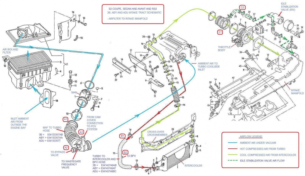
The 3B and ABY-powered S2s and the ADU powered RS2s have a fairly simple turbo to intake system, as shown here as an AAN schematic (3B/ABY/ADU details obviously vary - be patient, 3B/ABY/ADU specific info to follow below) (NOTE: Hyperlinks are underlined - click for more info):
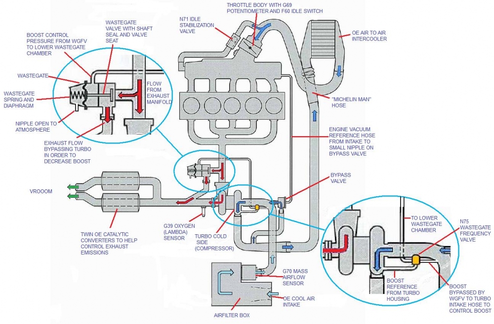
However, there are at least six other systems that are connected to the 3B/ABY/ADU turbo system. These other systems include:
1. The bypass valve system,
2. The N80 Evaporative Emissions Control System,
3. The Crankcase Ventilation system,
4. The N75 Waste Gate Frequency Valve (WGFV) system.
5. The Fuel Pressure Regulating Valve system.
6. The N71 Idle Stabilization Valve (ISV)
There are rubber and metal components of all four systems that have and/or will fail at some point, allowing boost pressure (and air) to go missing. This results in poor performance and, sometimes, a check engine code because the ECU recognizes that less air than expected showed up at the engine.
The purpose of this post is to identify the most likely causes of the boost/air leak and how to find them.
The possible sources of a boost leak, based on highest to lowest probablilty, include the following:
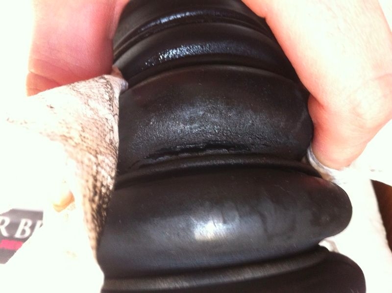
1. The boost hoses from the turbo to the intercooler and from the intercooler to the throttle body, particularly hose from the intercooler outlet to the intake pipe that runs along the top side of the cam cover. This "Michelin Man" hose is corrugated and made of rubber. Oily vapours tend to condense inside the hose and lay in the valleys of the corrugations. This rots and weakens the rubber until the point where it splits, causing a massive boost leak. At that point you really don't need a boost leak test. This post is intended to help you find the leak before it is massive so you can replace the hose before it fails catastrophically.
Here's a photo from AudiHeel(GoHeels) showing the way the rubber rots and eventually splits:
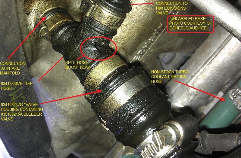
2. The "Tee" hose where the N80 Evaporative Emissions Control System and Crankcase Ventilation system connect into the intake manifold. Here is one example of one such "Tee" hose with a split, upstream of the PCV system one-way valve (happens to be on an AAN but 3B/ABY/ADUs have the same idea and same part number)
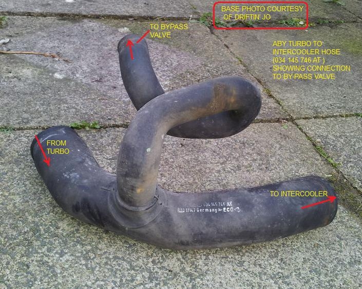
3. The other hoses and pipes between the turbo and the throttle body, including those cut or bent by over-zealous clamp tightening.
Here is an example ABY turbo to intercooler hose showing the branch to the By-pass valve (BPV):
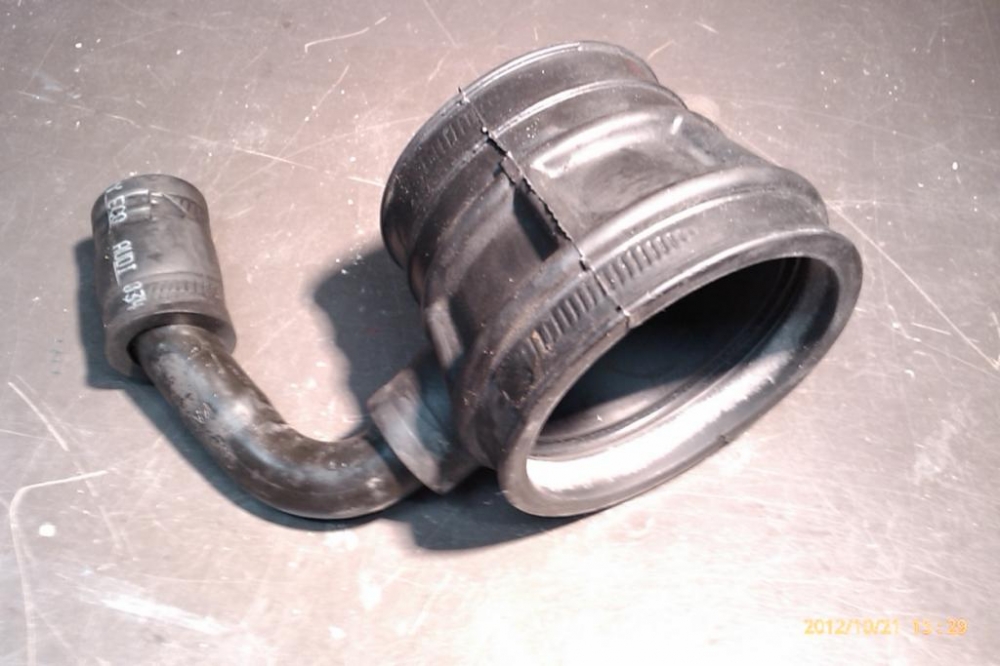
Here is a photo of the rubber boot that connects the intake pipe that runs along side of the cam cover to the throttle body. It apparently sometimes gets old, soft and splits. Note that this photo also shows the branch from the boot that connects to the ISV. These two hoses constitute plugging locations C1 and C2 in the diagram below.
Here is an example of the intake pipe to throttle body hose that shows a split just where the clamp is located. The owner of the RS2 in question, Mr. G said "What made this one very difficult was because the tear was at the bottom of the hose. When the hose was removed, visually looking at the hose didn't show the tear, we only found it by stretching the hose to see the tear."
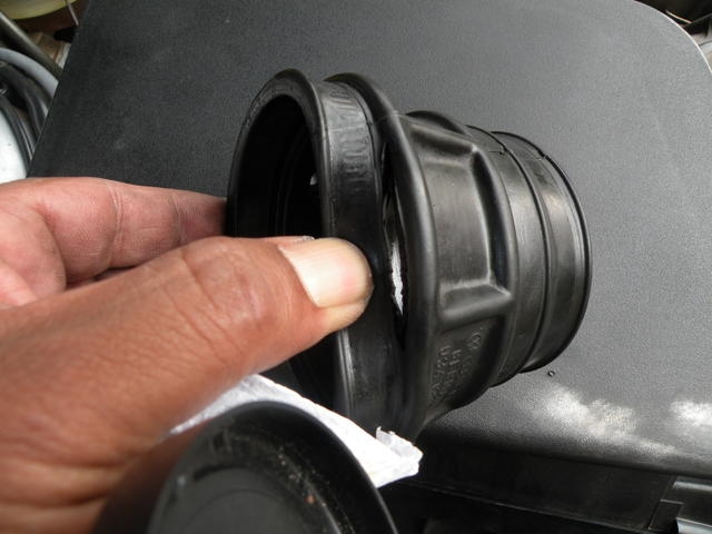
Photo courtesy of Mr. G
4. Other components of the Crankcase ventilation system, including the one-way bleeder valve and the pressure regulating valve and any and all plastic, metal and rubber piping.

.jpg)
Photos courtesy of Autohauz and ECS Tuning
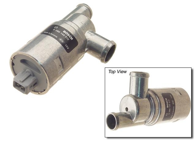
5. The N71 Idle Stabilization Valve (ISV) (plastic bits crack and leak) and the attendant hoses and pipes between the ISV and the back of the intake manifold.
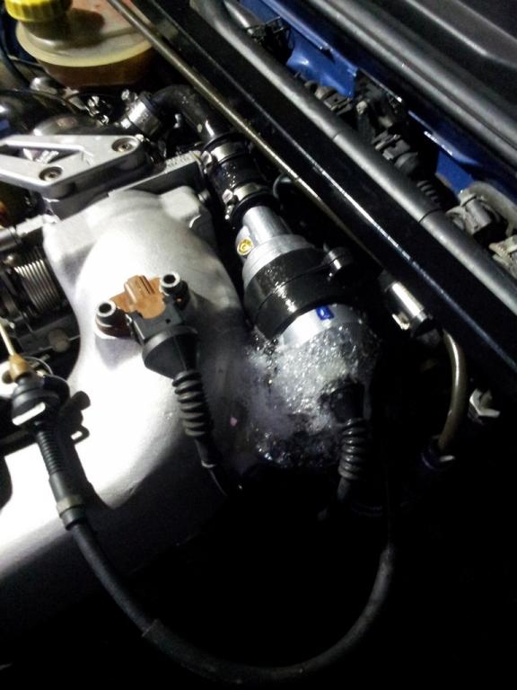
Here is an ISV valve showing leaking during a 3B/ABY/ADUboost test.
Thanks to ?? for the photo.
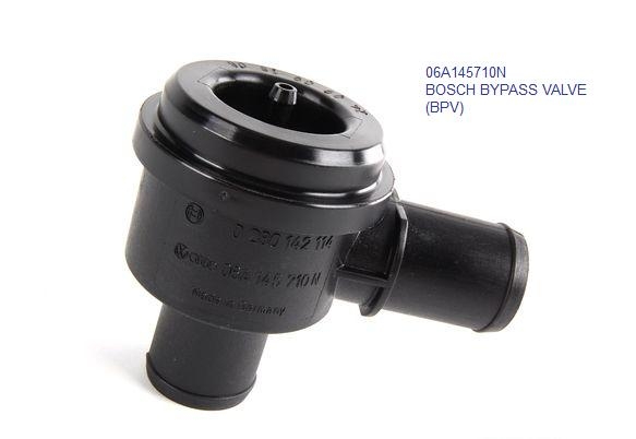
6. The Bypass Valve
7. The N80 Evaporative Emissions Control System valve
8. The N75 Waste Gate Frequency Valve and its attendant vacuum lines.
9. The vacuum lines between the intake manifold and the Fuel pressure regulator and the Moisture Trap and The G71 Manifold Absolute Pressure (MAP) sensor (in the ECU)
Here are four diagrams that contain the info needed to methodically think through the boost testing procedures and what you are looking for.
The 3B/ABY/ADU intake tract from air cleaner to throttle body (note labels (A1),(B2), (C1) etc):
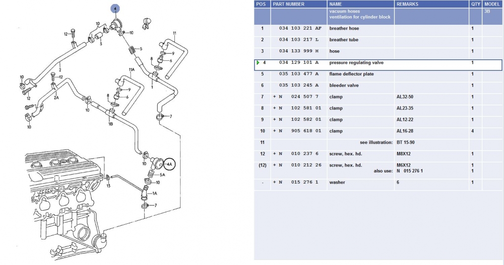
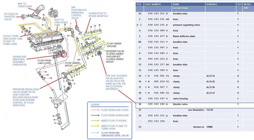
The 3B Crankcase Ventilation system diagram (Note Items 4 and 6):
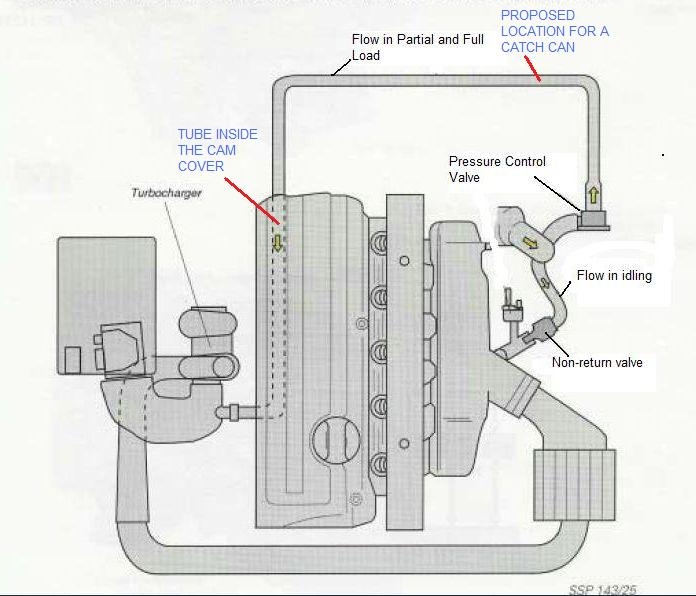
The ABY (and ADU) Crankcase Ventilation system diagram (Note Items 3 and 20 (and 21))
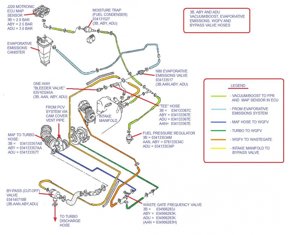
The N80 Evaporative Emissions System, he WGFV and BPV vacuum lines, and the vacuum/boost lines to the fuel pressure regulator, the moisture trap and the MAP sensor:
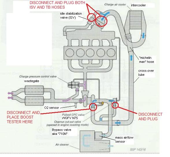
Here is a schematic diagram that shows a boost test that focuses only on the boost hoses and intercooler between the turbo and the throttle body (happens to be an AAN but 3B/ABY/ADU are all the same, schematically) (Option 6 below):
Testing for boost leaks involves introducing controlled pressure, i.e. 10 to 15 psi (0.7 to 1.1 Bar) from an air compressor into a non-running engine, with a pressure testing bung, such as shown in the diagram below and various other hoses plugged off (as appropriate to that test).
Here is an example boost testing cap with an air hose fitting (could also be a metal Schrader valve) to introduce the air and then monitor with a pressure gauge.
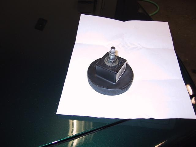
Photo courtesy of 4Driver4 (Tom M.)
Having a spray bottle filled with a very soapy water solution to spray onto the suspect parts (bubbles = leaks) is useful (the leak might be small and it might not produce a noticeable sound)
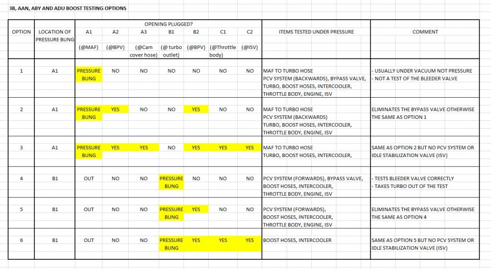
Here is a table that outlines the various boost testing options based on the above diagrams. Note: The table was set up to isolate certain components. Many people, most notably prj (dmitri) have suggested that the simplest method of boost leak testing that captures all the possibilities in one go is to place the pressure bung in "A1" in the diagram and disconnect the hose from the cam cover to "A3" and plug "A3", leaving the rest alone. This falls some where between test Option 1 and Option 3.
There are probably some minor errors in the above that will be corrected after people make their comments and provide their suggestions.
ADDITIONAL PHOTOS WELCOMED.
Thanks to those who contributed photos and diagrams used in this post.
AAN boost testing is already done but needs to be revised and converted to vBulletin format for here.
The 200 20VT boost testing is out for review (could have been combined with this one but I posted it on a North American forum in vBulletin format (we got 3B 200 20VTs but no S2s) so I thought I might as well port it over here intact).
/The staff at STFA.
However, there are at least six other systems that are connected to the 3B/ABY/ADU turbo system. These other systems include:
1. The bypass valve system,
2. The N80 Evaporative Emissions Control System,
3. The Crankcase Ventilation system,
4. The N75 Waste Gate Frequency Valve (WGFV) system.
5. The Fuel Pressure Regulating Valve system.
6. The N71 Idle Stabilization Valve (ISV)
There are rubber and metal components of all four systems that have and/or will fail at some point, allowing boost pressure (and air) to go missing. This results in poor performance and, sometimes, a check engine code because the ECU recognizes that less air than expected showed up at the engine.
The purpose of this post is to identify the most likely causes of the boost/air leak and how to find them.
The possible sources of a boost leak, based on highest to lowest probablilty, include the following:
1. The boost hoses from the turbo to the intercooler and from the intercooler to the throttle body, particularly hose from the intercooler outlet to the intake pipe that runs along the top side of the cam cover. This "Michelin Man" hose is corrugated and made of rubber. Oily vapours tend to condense inside the hose and lay in the valleys of the corrugations. This rots and weakens the rubber until the point where it splits, causing a massive boost leak. At that point you really don't need a boost leak test. This post is intended to help you find the leak before it is massive so you can replace the hose before it fails catastrophically.
Here's a photo from AudiHeel(GoHeels) showing the way the rubber rots and eventually splits:
2. The "Tee" hose where the N80 Evaporative Emissions Control System and Crankcase Ventilation system connect into the intake manifold. Here is one example of one such "Tee" hose with a split, upstream of the PCV system one-way valve (happens to be on an AAN but 3B/ABY/ADUs have the same idea and same part number)
3. The other hoses and pipes between the turbo and the throttle body, including those cut or bent by over-zealous clamp tightening.
Here is an example ABY turbo to intercooler hose showing the branch to the By-pass valve (BPV):
Here is a photo of the rubber boot that connects the intake pipe that runs along side of the cam cover to the throttle body. It apparently sometimes gets old, soft and splits. Note that this photo also shows the branch from the boot that connects to the ISV. These two hoses constitute plugging locations C1 and C2 in the diagram below.
Here is an example of the intake pipe to throttle body hose that shows a split just where the clamp is located. The owner of the RS2 in question, Mr. G said "What made this one very difficult was because the tear was at the bottom of the hose. When the hose was removed, visually looking at the hose didn't show the tear, we only found it by stretching the hose to see the tear."
Photo courtesy of Mr. G
4. Other components of the Crankcase ventilation system, including the one-way bleeder valve and the pressure regulating valve and any and all plastic, metal and rubber piping.
Photos courtesy of Autohauz and ECS Tuning
5. The N71 Idle Stabilization Valve (ISV) (plastic bits crack and leak) and the attendant hoses and pipes between the ISV and the back of the intake manifold.
Here is an ISV valve showing leaking during a 3B/ABY/ADUboost test.
Thanks to ?? for the photo.
6. The Bypass Valve
7. The N80 Evaporative Emissions Control System valve
8. The N75 Waste Gate Frequency Valve and its attendant vacuum lines.
9. The vacuum lines between the intake manifold and the Fuel pressure regulator and the Moisture Trap and The G71 Manifold Absolute Pressure (MAP) sensor (in the ECU)
Here are four diagrams that contain the info needed to methodically think through the boost testing procedures and what you are looking for.
The 3B/ABY/ADU intake tract from air cleaner to throttle body (note labels (A1),(B2), (C1) etc):
The 3B Crankcase Ventilation system diagram (Note Items 4 and 6):
The ABY (and ADU) Crankcase Ventilation system diagram (Note Items 3 and 20 (and 21))
The N80 Evaporative Emissions System, he WGFV and BPV vacuum lines, and the vacuum/boost lines to the fuel pressure regulator, the moisture trap and the MAP sensor:
Here is a schematic diagram that shows a boost test that focuses only on the boost hoses and intercooler between the turbo and the throttle body (happens to be an AAN but 3B/ABY/ADU are all the same, schematically) (Option 6 below):
Testing for boost leaks involves introducing controlled pressure, i.e. 10 to 15 psi (0.7 to 1.1 Bar) from an air compressor into a non-running engine, with a pressure testing bung, such as shown in the diagram below and various other hoses plugged off (as appropriate to that test).
Here is an example boost testing cap with an air hose fitting (could also be a metal Schrader valve) to introduce the air and then monitor with a pressure gauge.
Photo courtesy of 4Driver4 (Tom M.)
Having a spray bottle filled with a very soapy water solution to spray onto the suspect parts (bubbles = leaks) is useful (the leak might be small and it might not produce a noticeable sound)
Here is a table that outlines the various boost testing options based on the above diagrams. Note: The table was set up to isolate certain components. Many people, most notably prj (dmitri) have suggested that the simplest method of boost leak testing that captures all the possibilities in one go is to place the pressure bung in "A1" in the diagram and disconnect the hose from the cam cover to "A3" and plug "A3", leaving the rest alone. This falls some where between test Option 1 and Option 3.
There are probably some minor errors in the above that will be corrected after people make their comments and provide their suggestions.
ADDITIONAL PHOTOS WELCOMED.
Thanks to those who contributed photos and diagrams used in this post.
AAN boost testing is already done but needs to be revised and converted to vBulletin format for here.
The 200 20VT boost testing is out for review (could have been combined with this one but I posted it on a North American forum in vBulletin format (we got 3B 200 20VTs but no S2s) so I thought I might as well port it over here intact).
/The staff at STFA.


Comment