Vcds test

Collapse
X
 
  • Time
  • Show
Clear All
new posts
  • twoqu
    S2Forum Possessed
    • Sep 2003
    • 3103

    #31
    If the engine runs we have to assume that the relay is ok as both the injectors and these components are fed power from the same contact within the relay but have seperate fused supplies.
    So that leaves the connection between the relay and the fuse, the fuse, and the wiring from the fuse to the connectors to the components.
    We can test for power (12V+) or continuity. For example you can see if there is power at the fuse by probing the metal top and earth or test for contnuity by measuring continuity across the metal strips at the top by using the OHMS setting not the voltage. If it reads 0 Ohms its ok, if it reads 1 it is blown.
    Don't forget it needs to be with the engine running to get voltage readings but not continuity.

    Comment

    • bilko0795
      S2Forum Extremist
      • Feb 2011
      • 1883
      • Country: Wales

      #32
      Originally posted by twoqu
      If the engine runs we have to assume that the relay is ok as both the injectors and these components are fed power from the same contact within the relay but have seperate fused supplies.
      So that leaves the connection between the relay and the fuse, the fuse, and the wiring from the fuse to the connectors to the components.
      We can test for power (12V+) or continuity. For example you can see if there is power at the fuse by probing the metal top and earth or test for contnuity by measuring continuity across the metal strips at the top by using the OHMS setting not the voltage. If it reads 0 Ohms its ok, if it reads 1 it is blown.
      Don't forget it needs to be with the engine running to get voltage readings but not continuity.
      Just tested them again and the ISV is showing 0.03 volts also checked fuse 24 and was showing 14.32v also checked s27 and that was 3.65v. Would the ecu have anything to do with the problem?

      Comment

      • UrS4boy
        S2Forum Obsessed
        • Feb 2006
        • 11859
        • Country: Canada

        #33
        Originally posted by bilko0795
        Just tested them again and the ISV is showing 0.03 volts also checked fuse 24 and was showing 14.32v also checked s27 and that was 3.65v. Would the ecu have anything to do with the problem?
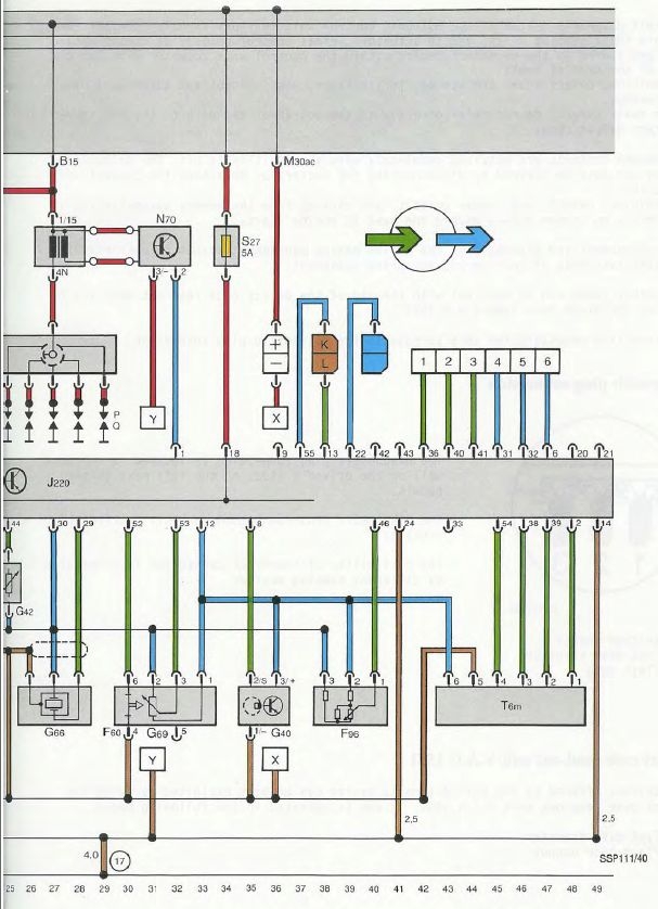
        The diagram below is for a 3B Motronic but I think the S27 is the power feed to the ABY and ADU ECUs at pin T55/18 (Pin T55/18 is the power for the AAN ECY (different fuse number though)). S27 is fed off the No. 30 constant power bus (not switched) so the voltage, if measured properly, should be about 11.7 VDC coming into S27 with the engine off and about 14 VDC with the engine running. 3.65V isn't right. Many of the devices that the ECU controls are 0 -5 VDC stepped down from nominal 12 VDC so if you are feeding the ECU with only 3.65 V then there is bound to be device control issues.

        RS2'd 93 UrS4 5 spd sedan
        94 UrS4 V8 6 spd manual avant

        Comment

        • twoqu
          S2Forum Possessed
          • Sep 2003
          • 3103

          #34
          Check both sides of the fuse for voltage to rule it out.
          If you have voltage on both sides and none at the components then it can only be the wiring, although its a bit odd that all three are dead. You will need to check for continuity from the connector back to the fuse from each.
          Either there is a break in the wiring directly after the fuse or somehow all three supplies are broken or there is an issue with the connector plugs themselves.
          Not sure how you are probing but its a good idea to peel back the rubber boots so you can see what you are doing as per the pics Dave provided.
          We can rule the relay out if there is power at the fuse. You just need to systematically work out where the power disappears!

          Comment

          • bilko0795
            S2Forum Extremist
            • Feb 2011
            • 1883
            • Country: Wales

            #35
            Here is a picky of the meter reading from the N71


            And this is the reading from the N75

            Comment

            • twoqu
              S2Forum Possessed
              • Sep 2003
              • 3103

              #36
              Are you using the same earth point for all the readings? A quick check is to touch a fuse to check you get the expected reading and then probe the connector. The inlet manifold grounds are a good source of earth underbonnet!

              Comment

              • UrS4boy
                S2Forum Obsessed
                • Feb 2006
                • 11859
                • Country: Canada

                #37
                At this point, I think the critical issue is to confirm/deny that the voltage into and out of the S27 is 12 V nominal. If there isn't 12 V nominal, no sense probing anything else until that is sorted properly.

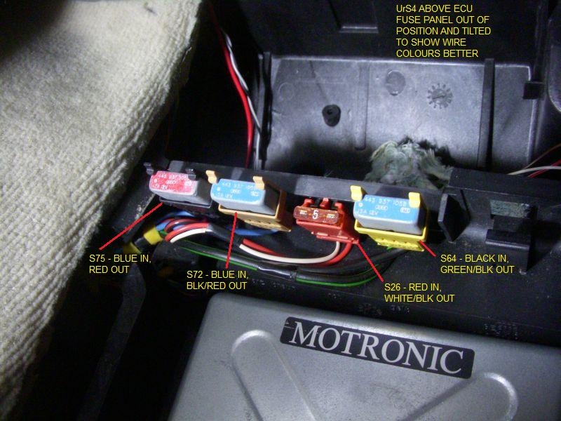
                I don't have a good S2/RS2 photo of the S27 ECU fuse wiring (hint, hint) but I do have the equivalent C4 UrS4/S6 photo for their S26 ECU fuse (see below). To probe input power to the fuse, you would remove the 5 Amp spade connector and put the (+) probe of your DMM (set to 20 VDC) into the female connector attached to the red wire; the (-) (ground/earth) probe would go to some thing metal that is handy (scuttle, head, intake manifold, etc). Should be 12 V nominal even with the ignition off and engine off.

                To test the output from the S26 (S27 in the S2/RS2 example), you would put a good fuse back in the fuse holder and probe from the back of the connector, touching the back of the pin with the white/black wire (for the UrS4/S6 S26 example) with the (+) probe, grounding as before. See below, the output wire for the S27 in an RS2 (and probably S2s) is red/white.


                Diagram from Paul N's S2central.net
                RS2'd 93 UrS4 5 spd sedan
                94 UrS4 V8 6 spd manual avant

                Comment

                • bilko0795
                  S2Forum Extremist
                  • Feb 2011
                  • 1883
                  • Country: Wales

                  #38
                  Originally posted by twoqu
                  Are you using the same earth point for all the readings? A quick check is to touch a fuse to check you get the expected reading and then probe the connector. The inlet manifold grounds are a good source of earth underbonnet!

                  Yes same earth point to check the fuse as well as the connector going to change the ECU tomorrow as I have a spare just to eliminate possible causes. I am probably clutching at straws.

                  Comment

                  • UrS4boy
                    S2Forum Obsessed
                    • Feb 2006
                    • 11859
                    • Country: Canada

                    #39
                    Originally posted by bilko0795
                    Yes same earth point to check the fuse as well as the connector going to change the ECU tomorrow as I have a spare just to eliminate possible causes. I am probably clutching at straws.
                    Clutch at the S27 straw first. A new ECU won't solve a low input voltage issue.
                    RS2'd 93 UrS4 5 spd sedan
                    94 UrS4 V8 6 spd manual avant

                    Comment

                    • bilko0795
                      S2Forum Extremist
                      • Feb 2011
                      • 1883
                      • Country: Wales

                      #40
                      Dave I will try that over the w/end and will also try and get some photo's of the wiring for you I am no David Bailey mind

                      Comment

                      • twoqu
                        S2Forum Possessed
                        • Sep 2003
                        • 3103

                        #41
                        Well to be honest I can't see how thats going to help as we have established its most likely a wiring problem IF what you have reported back to us it correct. The ecu does not directly power those components it only signals the FP relay to do so. Power at the fuse indicates thats happening!
                        It takes a few minutes to identify the problem if you are willing to do what has been suggested and feedback the results.

                        Comment

                        • twoqu
                          S2Forum Possessed
                          • Sep 2003
                          • 3103

                          #42
                          Double check that S27 voltage with ignition on and with car started to see what the voltage is. Usually ecu's are intolerant of low voltage, indeed if it is genuinely below 6V it would trigger a fault code which you can double check.

                          Comment

                          • UrS4boy
                            S2Forum Obsessed
                            • Feb 2006
                            • 11859
                            • Country: Canada

                            #43
                            Originally posted by twoqu
                            Double check that S27 voltage with ignition on and with car started to see what the voltage is. Usually ecu's are intolerant of low voltage, indeed if it is genuinely below 6V it would trigger a fault code which you can double check.
                            Agree. At this point, without confirmed good data, I don't know what is going on. If the engine starts, then they fuel pump relay is working and should be supplying power to the S24 which should put 13.7 VDC to the non-ground side of the N71, N75 and N80 connectors coming in on the Blue/red wire at each of those connectors.

                            Note Trace [8] to Trace [50] (on second diagram below (source S2central.net))


                            Note Trace [50] from Trace [8]
                            RS2'd 93 UrS4 5 spd sedan
                            94 UrS4 V8 6 spd manual avant

                            Comment

                            • twoqu
                              S2Forum Possessed
                              • Sep 2003
                              • 3103

                              #44
                              Just checked a loom and the feed out of S24 is one wire which means that somewhere in the loom there is a crimped junction where the three supplies are joined. Sometimes you have multiple feeds.
                              You could also seperate the WGFV seperate loom to check for power at the connector from the main loom.
                              As its all three, the bad news is that if the single feed wire to the crimp is broken or detached, it will be a ballache to find and repair. The most obvious culprit in case of no power to common components would be the fuse. That can be checked with the MM by either measuring its resistance (0) or checking for voltage on both sides.
                              Talking of fuses, it might be worth checking that S27 for resistance or corrosion in the holder.

                              For Dave: Looks like there is a confusing error on the wiring schematics as it states that connection D9 (which is the crimp I guess) is via S27 when its actually S24. The other schematics shows S27 directly feeding the ecu from the permanent 12V feed.
                              Last edited by twoqu; 2 May 2014, 16:17.

                              Comment

                              • UrS4boy
                                S2Forum Obsessed
                                • Feb 2006
                                • 11859
                                • Country: Canada

                                #45
                                Originally posted by twoqu
                                ...For Dave: Looks like there is a confusing error on the wiring schematics as it states that connection D9 (which is the crimp I guess) is via S27 when its actually S24. The other schematics shows S27 directly feeding the ecu from the permanent 12V feed.
                                Robin: I might be missing something but I don't see either problem (I might see it as I try to explain it below)

                                1. Starting with the S27 feed to the ECU:


                                2. The (D9) crimp (typically a round copper crimp) shows feeding the N71, N75 and N80 below, with power coming into the crimp (at trace [50] ) from trace [8]:


                                If you go back to trace [8] it clearly shows current flow from the downstream side of the S24 fuse via a blue/red wire , which is fed from pin 87a on the J17 Fuel Pump relay via a green/black wire. I don't see the confusion. What am I missing?


                                3. The D9 crimp also shows connections to traces [67] and [20]. For curiosity, I found these:

                                a) The connection to [20] from the (D9) crimp on trace [52] is a trailer recognition unit J345, which presumably resulted in modified ECU mapping and speed limiters while towing a trailer with an RS2 (so not very relavent to the discussion here) (but I had to check):


                                b) The connection to [67] from the (D9) crimp on trace [51] goes to the J155 after-run turbo coolant pump - again, interesting but not very relavent to the N71, N75 and N80 discussion, but it does complete the cycle of life (queue Elton John song):

                                RS2'd 93 UrS4 5 spd sedan
                                94 UrS4 V8 6 spd manual avant

                                Comment

                                Working...