
In searching for a solution to my hot re-start issue with my UrS4 (after getting no improvement by replacing the G4 crank sensor with a US$205 one), I decided to check out the MAF. As I did so, I checked the pins, cleaned them and added Stabilant 22A contact enhancer.
This is the info that I just added to my G70 MAF post:
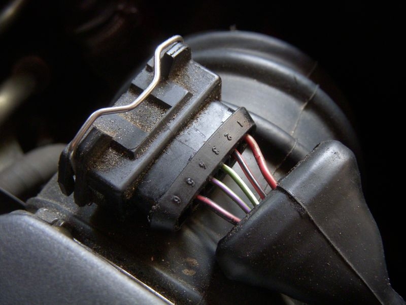
For the G70 MAF harness connector the female pins are only in positions 1 through 5; No. 6 the one at the left end of the connector is empty. For the AAN MAF harness connector, the five pins are as follows:
Pin 1 = Brown with red stripe, goes to a ground (16) (on the cylinder head (cam) cover)
Pin 2 = Red with black stripe, goes to pin T26/55 in the ECU
Pin 3 = Green with white stripe, goes to pin T7/55 in the ECU
Pin 4 = Green with purple (violet) stripe, goes to pin T25/55 in the ECU. This is the burn-off signal wire from the Holding Relay
Pin 5 = Black with red stripe, connects to the fuel injector harness
Here is a photo showing those five AAN wires:
Testing the G70 MAF is found in the Bentley in section J24, Volume One, pgs. J24-77 to J24-85. The following is a short-form summary of this info and is not complete:
1. Testing for ground: Disconnect the harness connector from the MAF. Set your DMM to 20 ohms and look for continuity between Pin 1 (Pin 6 is the empty position) and ground on the engine or chassis. Not continuity = you have a ground issue involving that Brown/red wire. Start tracing back, looking for a broken wire. Won't be fun.
2. Testing for connection to the injector circuit: Turn the DMM to 20 VDC. Connect to Pin 5 and ground. Turn on the ignition. You should get some positive DC volts.
3. Checking MAF function: With harness connector removed, switch DMM to 200 ohms. Connect DMM probes to terminals 1 and 2 on the MAF (1 is on the right, 6 is on the left). Record the resistance. Disconnect leads and "Short" the circuit (press probe ends together). Display value must equal value recorded previously.
If the difference is greater than 0.1 Ohm, replace MAF.
Re-connect the MAF sensor harness connector. Peel back the rubber boot on the connector to expose the terminals. Switch the DMM to 20 VDC. Connect the DMM to the back side of Terminals 1 and 3. Turn the ignition switch to "ON" (run) but don't start the engine. Should be 1.2 to 1.5 Volts. Start the engine and let idle. Voltage reading should now be 2.5 volts. Increase the engine speed briefly (manually move the throttle position to more open). Voltage should increase to 3.0 to 5.0 volts (depending on engine speed). All the of the specified voltages must be obtained. If NO = replace MAF.
There is more re: Holding relay/burn-off wire but that shouldn't directly affect running and idling.
The full G70 MAF post: http://forums.quattroworld.com/s4s6/msgs/20442.phtml
This is the info that I just added to my G70 MAF post:
For the G70 MAF harness connector the female pins are only in positions 1 through 5; No. 6 the one at the left end of the connector is empty. For the AAN MAF harness connector, the five pins are as follows:
Pin 1 = Brown with red stripe, goes to a ground (16) (on the cylinder head (cam) cover)
Pin 2 = Red with black stripe, goes to pin T26/55 in the ECU
Pin 3 = Green with white stripe, goes to pin T7/55 in the ECU
Pin 4 = Green with purple (violet) stripe, goes to pin T25/55 in the ECU. This is the burn-off signal wire from the Holding Relay
Pin 5 = Black with red stripe, connects to the fuel injector harness
Here is a photo showing those five AAN wires:
Testing the G70 MAF is found in the Bentley in section J24, Volume One, pgs. J24-77 to J24-85. The following is a short-form summary of this info and is not complete:
1. Testing for ground: Disconnect the harness connector from the MAF. Set your DMM to 20 ohms and look for continuity between Pin 1 (Pin 6 is the empty position) and ground on the engine or chassis. Not continuity = you have a ground issue involving that Brown/red wire. Start tracing back, looking for a broken wire. Won't be fun.
2. Testing for connection to the injector circuit: Turn the DMM to 20 VDC. Connect to Pin 5 and ground. Turn on the ignition. You should get some positive DC volts.
3. Checking MAF function: With harness connector removed, switch DMM to 200 ohms. Connect DMM probes to terminals 1 and 2 on the MAF (1 is on the right, 6 is on the left). Record the resistance. Disconnect leads and "Short" the circuit (press probe ends together). Display value must equal value recorded previously.
If the difference is greater than 0.1 Ohm, replace MAF.
Re-connect the MAF sensor harness connector. Peel back the rubber boot on the connector to expose the terminals. Switch the DMM to 20 VDC. Connect the DMM to the back side of Terminals 1 and 3. Turn the ignition switch to "ON" (run) but don't start the engine. Should be 1.2 to 1.5 Volts. Start the engine and let idle. Voltage reading should now be 2.5 volts. Increase the engine speed briefly (manually move the throttle position to more open). Voltage should increase to 3.0 to 5.0 volts (depending on engine speed). All the of the specified voltages must be obtained. If NO = replace MAF.
There is more re: Holding relay/burn-off wire but that shouldn't directly affect running and idling.
The full G70 MAF post: http://forums.quattroworld.com/s4s6/msgs/20442.phtml





Comment