Cooling fan testing

Collapse
X
 
  • Time
  • Show
Clear All
new posts
  • UrS4boy
    S2Forum Obsessed
    • Feb 2006
    • 11859
    • Country: Canada

    #31
    S2 after-run pump and fan wiring schematics

    Originally posted by Monkeymagic
    Urs4 boy. Trust me I've tried! ...what's next the 324 control module?
    If shorting the two wires on the two pin switch on the water manifold together brings the after-run pump on, as per my after-run system description above, that means that the 324 after-run pump and fan control module is *probably* working fine. I say
    "probably" because at least the one channel is working, i.e. taking the after-run pump power to ground.

    To be 100% confident about the 324 (J155), you'd have to check whether the 5/87a pin opens up a connection to ground for the J69 (214) after-run fan relay. Note: There is still the question of the fuse that is in line between the alway hot "30" and the J69 (214) fan relay.

    Note: I have created this diagram for the S2 based on S2Central's S2 wiring pdf (http://www.s2central.net/S2_Schematics/A/A17.PDF). In doing so, I discovered two things:

    1. The C4 UrS J69 (214) fan relay is called a J138 on the S2.
    2. There is a resistor in series with the fan in Stage 1 that my C4 UrS diagram did not show.

    As a result, if a S2 after-run fan is not coming on but the V51 After-run pump is coming on, you need to check the S5 fuse, the S20 fuse, and the N47.

    Attached Files
    Last edited by UrS4boy; 7 September 2014, 15:24. Reason: Correct error in labeling in diagram
    RS2'd 93 UrS4 5 spd sedan
    94 UrS4 V8 6 spd manual avant

    Comment

    • Monkeymagic
      S2Forum Possessed
      • Mar 2012
      • 3419
      • Country: England

      #32
      Thank you. I have checked fuse 5 and 20 they are intact. Is n47 the resistor seated below the rad fan motor? Of so it looks a bit shabby I guess it's effectively a thermal fuse?

      Comment

      • UrS4boy
        S2Forum Obsessed
        • Feb 2006
        • 11859
        • Country: Canada

        #33
        Originally posted by Monkeymagic
        Thank you. I have checked fuse 5 and 20 they are intact. Is n47 the resistor seated below the rad fan motor? Of so it looks a bit shabby I guess it's effectively a thermal fuse?
        I just updated that schematic with some photos of the fuse box and the under-dash relay panel to point you closer to the answer. Go back and have a look (it might help - or not).

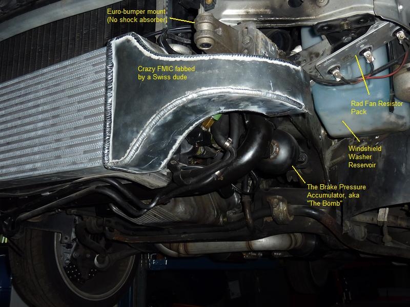
        As for the fan resistors, all I can say is for a C4 UrS, there are three fan resistors on a metal plate for the 3 fan speed stages, as shown in this photo (apologies to the "Crazy Swiss Dude"):

        RS2'd 93 UrS4 5 spd sedan
        94 UrS4 V8 6 spd manual avant

        Comment

        • Monkeymagic
          S2Forum Possessed
          • Mar 2012
          • 3419
          • Country: England

          #34
          coolant fan

          The only thing i can find resembling a resistor looks like this with the exception of the wiring.
          Attached Files

          Comment

          • Monkeymagic
            S2Forum Possessed
            • Mar 2012
            • 3419
            • Country: England

            #35
            Again excuse my inability to decipher the wiring diagrams properly. As I have a full speed fan, a working after run pump and all fuses and relays appear good I'm beginning to think the obvious weak link is the resistor.
            Am I right to assume this?

            Is there a way to test the resistor before throwing money at it?

            the part number for the series resistor for the 3B according to ETKA is 433 959 493A

            Comment

            • johne
              S2Forum Extremist
              • Apr 2007
              • 1405
              • Country: United Kingdom

              #36
              Just a note of caution here, the 3B and ABY arrangements for the radiator fan resistor are different.

              The picture Dave has posted is correct but for ABY. Also, for the record, the thermal switch in the radiator is wired differently on ABY depending if air-con is fitted or not.

              John

              Comment

              • twoqu
                S2Forum Possessed
                • Sep 2003
                • 3103

                #37
                All the info to help has already been posted.
                The resistor is quoted as being 0.9 ohms. So if you MM is accurate enough it should be possible to measure it. The purpose of the resistor is to give you the first stage speed (ohms law and all that). The second stage (normal) is achieved by the fan first speed getting a full 12V.
                Just pull the fan connector and measure for voltage at the fan first stage terminal. It should be 12V+ by bridging the rad switch and less when bridging the after run switch. If you have voltage at the connector then its pointing to the fans first stage being dead. This would not effect necessarily the fans second stage.
                The 3B unlike the ABY used this resistor and a two stage fan to get 3 speeds. The ABY used the resistor pack and a one speed fan to do the same by passing power through various resistance stages to decrease speed.

                Comment

                • Monkeymagic
                  S2Forum Possessed
                  • Mar 2012
                  • 3419
                  • Country: England

                  #38
                  Thankyou. Johne has kindly offered to cast an eye over it for me. I will post the findings.
                  many thanks ste

                  Comment

                  • UrS4boy
                    S2Forum Obsessed
                    • Feb 2006
                    • 11859
                    • Country: Canada

                    #39
                    Originally posted by Monkeymagic
                    Again excuse my inability to decipher the wiring diagrams properly. As I have a full speed fan, a working after run pump and all fuses and relays appear good I'm beginning to think the obvious weak link is the resistor.
                    Am I right to assume this?... The part number for the series resistor for the 3B according to ETKA is 433 959 493A
                    I can confirm the PN and your logic (hopefully we aren't both wrong). I am going to leave you will these three photos/diagrams and wish you luck.


                    Presumably the Item 20 dual switch is the combined F18/F54 switch in the diagram above.
                    Attached Files
                    RS2'd 93 UrS4 5 spd sedan
                    94 UrS4 V8 6 spd manual avant

                    Comment

                    • UrS4boy
                      S2Forum Obsessed
                      • Feb 2006
                      • 11859
                      • Country: Canada

                      #40
                      Originally posted by twoqu
                      ....The 3B unlike the ABY used this resistor and a two stage fan to get 3 speeds. The ABY used the resistor pack and a one speed fan to do the same by passing power through various resistance stages to decrease speed.
                      I guess that is my fault for using the 3B wiring diagrams at S2Central.net. I'm not sure if there are ABY diagrams or not available. Even if they were, I have wasted too much time today trying to be helpful.
                      RS2'd 93 UrS4 5 spd sedan
                      94 UrS4 V8 6 spd manual avant

                      Comment

                      • Monkeymagic
                        S2Forum Possessed
                        • Mar 2012
                        • 3419
                        • Country: England

                        #41
                        Please don't think I'm not appreciative of the help and effort you have gone to.
                        its just my brain struggles with such things. I am slowly working my way through the information and conducting tests.
                        the wealth of info on this forum is astonishing.

                        Comment

                        • Monkeymagic
                          S2Forum Possessed
                          • Mar 2012
                          • 3419
                          • Country: England

                          #42
                          Right I have had a look with a multi meter. If I bridge the outer terminals on the fan switch I get 12 volts at the fan. I knew that though as the fan works.
                          If I bridge the low speed terminals I get 12 volts at the fan on low speed terminals.
                          If I bridge the the after run terminals with ignition off I get a functioning pump and 12 volt at the low speed motor terminals. When I turn ignition on the pump stops and voltage drops to zero. Therefore suggesting the relays etc are in working order.
                          I put the mm on the resistor terminals and didn't get any reading except on the audible one where it reads 1.2and the audible buzzer sounds. I'm the first to admit I don't know what I'm doing there though.
                          Would this all point toward fan failure as it's been stated the low speed is regulated by the fan?

                          Comment

                          • UrS4boy
                            S2Forum Obsessed
                            • Feb 2006
                            • 11859
                            • Country: Canada

                            #43
                            Originally posted by Monkeymagic
                            Right I have had a look with a multi meter.
                            Good on you. You are definitely close to getting this sussed.

                            BTW: The 324 After-run pump and fan control module has a switched power input that results in the 324 only being energized and prepared to function when the ignition is off. As a result, your comment about what happened when the ignition was turned on was correct.

                            Carry on, you are almost there (BTW: I don't what the answer is but it does look like the fan motor/staging is definitely suspect (what about that N47 resistor pack?))

                            RS2'd 93 UrS4 5 spd sedan
                            94 UrS4 V8 6 spd manual avant

                            Comment

                            • twoqu
                              S2Forum Possessed
                              • Sep 2003
                              • 3103

                              #44
                              If you are getting voltage at the terminal then it establishes that the circuits are intact and functioning. So that does leave the fan first stage as the suspect.

                              Comment

                              • Monkeymagic
                                S2Forum Possessed
                                • Mar 2012
                                • 3419
                                • Country: England

                                #45
                                Brilliant I'll order a new motor. I'm not sure how to test the resistor/n47. I connected the tester to either side of the resistor and it made the audible buzz which I think showed continuity

                                Comment

                                Working...