You can change the style the forum displays by selecting your preferred style at the bottom left of the site.
We have made an enhancement so that old threads should now link from search results to the correct thread. This is not yet in place for single post links
You need a two-channel USB scope and log input to ECU from hall and crank sensors at the same time. Most likely the problem is there, no correct signal.
if the timing is out one teeth, may the ecu cuts fuel and spark??
Sure. As I said, cam sync.
If it's not sensors the engine can be timed up wrong.
If hall is in distributor and distributor is 180 degrees out, then you will have the same problem.
I think, want to believe, that the problem is wiring loom...
Ok, one teeth is enough for the ecu to cut fuel injectors and spark. Tomorrow i'll advance and retard one teeth, turn by hand to don't damage any valve and see what cr has, less or more
But first I'll check the things who I told in the wiring loom
I advanced and retarded 1,2,3 teeth the cam pulley and nothing. I checked the aligment of the cams and good, crank pulley good, flywheel good. Checked and compared, with my s2 3b pin swap, the voltaje and grounds...all the same, except pin 3 used to put in ground the fuel pump relay and I was thinking on using a relay, to see if when I crank the relay is activated...but I could use the multimeter to see if there are ground on it when I'm cranking
Actually I'm little bit tired...also I was thinking on remove the gearbox and fit a 3b flywheel and trie to start the engine
... Checked and compared, with my s2 3b pin swap, the voltaje and grounds...all the same, except pin 3 used to put in ground the fuel pump relay and I was thinking on using a relay, to see if when I crank the relay is activated...but I could use the multimeter to see if there are ground on it when I'm cranking
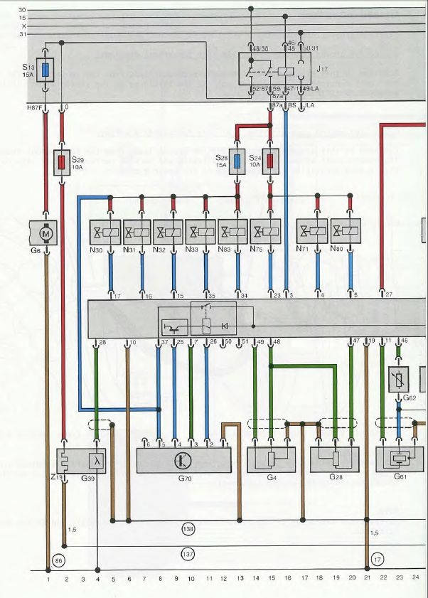
Pin 3 is very important to the J17 Fuel Pump Relay and the Fuel Pump Relay is *VERY* important to the operation of an UrS (S2, UrS4/S6 and RS2). IF there is a pin 3 issue, the engine will NEVER start.
The ECU takes the J17 to ground via its Pin T55/3 *ONLY* when it gets a signal from the G28 Engine Speed Sensor that tells the ECU that the engine is spinning at more than 13 RPM (on the starter). No such signal = no FP relay activation.
From the diagram below, it can be seen that the ECU to signal to the FP relay comes from Pin 3/55 of the ECU as a brown wire with a yellow stripe, i.e. a switched ground. This pulls power from the No. 15 switched power terminal under the drivers side knee bolster. With current allowed to run from 15 to ground (via pin 3/55 of the ECU), the relay's electromagnets engage two contacts which then pull power off the unswitched (always hot) 30 terminal. This allows current to flow from the 30 power line to the J17 relay power outlet terminals, 87A and 87F. Terminal 87A energizes the N75 wastegate frequency valve, the five injectors (which get their duty cycle control from the ECU), the idle stablization valve (N71) and the emissions carbon cannister frequency valve (N80). Terminal 87F energizes the G6 fuel pump (via a green wire to Fuse No. 17 and then a green wire with yellow stripe to the FP) and the G39 O2 sensor via a black wire to a 12 Amp circuit breaker located under the passenger side (right side) kick panel. (NOTE: Wire colours vary from AAN (above) to S2 and RS2).
The Audi Enthusiast website. Forums for all Audis including A4, S4, A5, S5, A6, S6, allroad, A8, S8, TT, R8, Q5, Q7, 4000, 100, 200, v6, v8, vintage, local forums
RS2'd 93 UrS4 5 spd sedan
94 UrS4 V8 6 spd manual avant
Thanks for your time mate, I know that it's a very important thing on a "stock" wiring...but I put switch positive for S24,S28 and S29, I don't use the fuel pump relay to feed these fuses. My question is if I also need to put in ground pin 3 or a relay to see if the ecu put in ground this relay or take the multimeter to check if the ecu send negative when the engine is cranking
Tomorrow if I have time I'll fit a relay between pin 3 and +12...maybe she wants to have a relay there or ground
If doesn't start I'm going to wait for the osciloscope
I checked the signals with the osciloscope, and happened one thing, when I was cranking I haven't got hall and firing point signals...then I turned the engine by hand (to turn it more slowly) with the spark plugs out and all the signals was good!! I put the spark plugs into the coils and I had spark and fuel(I could smell it), this turning the engine by hand
I fit again the spark plugs, I crank with the starter and nothing....I thought, maybe when I crank the voltaje is too low for the ecu...I unpluged the starter connector and turned the key to check the voltajes(like I was cranking but without the starter working), and I listen the relay "click" into the ecu, like when you put the contact on, automatically I checked the +12v switch, was good but when you turn the key to start the engine the voltaje drops to 0V!! I removed the wire from the fuse box to the batery and the engine started like a lightning, then I put the wire to other fuse box pin(the bigger one and protected) with +12v switched (also when I crank) and perfect
Thanks for your time and ideas, but finally was this stupid thing
The nightmare has finished, today I'm going to sleep like a stone
No no mate, the problem was that my +12v switched cut when I was cranking, when I put the contact on( position 1) I had +12v but when I turn the key to position 2 to start the engine, cut the voltaje...I was trying to start my engine with the ecu and coils off...I changed the +12v switch to other fuse box pin and perfect
No no mate, the problem was that my +12v switched cut when I was cranking, when I put the contact on( position 1) I had +12v but when I turn the key to position 2 to start the engine, cut the voltaje...I was trying to start my engine with the ecu and coils off...I changed the +12v switch to other fuse box pin and perfect
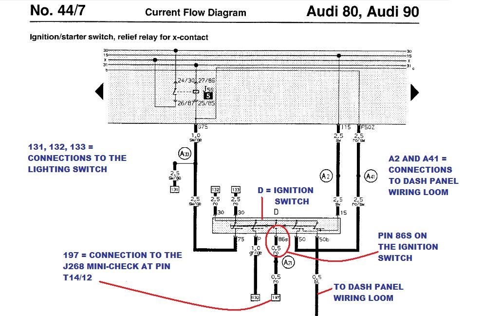
Sounds like you had it connected to ignition Pin 50, the load reduction circuit that cuts power during starting, rather than Ignition Pin 15 that is switched power in both "RUN" and "START".
The pin-out info references S2s and RS2s but the principle should be the same:
first "30" = thick red
second "30" = thick red
75 = black/yellow to load reduction relay (during starting)
P = green/yellow
86S = thin red
50 = red/black to J59 X-contact Load Relief Relay (power flows through it to other devices AFTER the engine has started (or at least the switch has been turned to the run position) = could include some circuit fuses like S12.
50b = thin blue
15 = *SWITCHED* POWER thick black that will feed lots of fuses, like S12, etc.
I think "15" is the one under the thumb on the left (photo is from ujimaflip)
So had it been put in the wrong place at some point in the past?
As UrS4boy said, I took the +12 switched from a wrong place...from the load reduction circuit, you have power but only with the the key on first position, when you crank not
Originally posted by UrS4boy
Sounds like you had it connected to ignition Pin 50, the load reduction circuit that cuts power during starting, rather than Ignition Pin 15 that is switched power in both "RUN" and "START".
That's it
I thought that it was on 30a and then I changed to O pin, it's the big white wire with black connector
Now all works perfect, tacho gauge works fine with the 2k ohms between signal wire and ground, water temp with the blue/brown(or blue/yellow...now I don't remember very good, but I think that was blue/brown) attached to brown/yellow MTFS connector and for the oil pressure warning bulb I changed the white pressure(Circuit N.O.) sensor for a black one(Circuit N.C.), and remove the oil relay, the only problem is that the black sensor works at a very low pressure...0,15/0,35bar and the white one works at 1,6/1,9bar...I need a N.C. who works at 1,6/1,9bar or fit a gauge to see the pressure
We process personal data about users of our site, through the use of cookies and other technologies, to deliver our services, personalize advertising, and to analyze site activity. We may share certain information about our users with our advertising and analytics partners. For additional details, refer to our Privacy Policy.
By clicking "I AGREE" below, you agree to our Privacy Policy and our personal data processing and cookie practices as described therein. You also acknowledge that this forum may be hosted outside your country and you consent to the collection, storage, and processing of your data in the country where this forum is hosted.







Comment