
 Tweet
Tweet
This is a first attempt. It is based on the previous one that I did for the AAN with additional inputs re: wire colours from Paul Nugent's S2Central.net (Thanks Paul). Needs review/checking and probably editing. I have corrected a few things, e.g. the N122 and N127 portion of the diagrams but there are issues with the diagram and other info regarding the G4 and G28 pins and wiring colours. At least we can start with this:

The PN of the ABY S2 ECU was 895907551A. The replacement was 895997551X

As twoqu (Robin) said: "Don't forget that there was immo versions of both ABY (551B) and ADU (551C). The part numbers with X in them represent exchange items."
Thanks for that Robin. It gave me the leads I needed to start tracking the PNs back to the beginning.
8A0907551B was replaced by 8A0997551X on 01/08/2002
8A0907551A was dropped and replaced by 895907551A (for the ABY) - no date noted
895907551A was replaced by 895997551X on 01/11/2002
895997551B (for the ABY) was replaced by 895997551AX on 01/05/2002
The RS2 ADU ECU PN shows up now as 8A0997551X or 8A0997551BX but was originally a 8A0907551C which was replaced the 8A0997551X on 01/05/2002
In playing with those PNs, I found this 8A0907551C photo in a pricy ebay.de RS2 ECU advert:
http://www.ebay.de/itm/Audi-Steuerge...-/262293472974

The main difference between the ABY and ADU ECUs are the chip sets and the ABY has a 250 kPa (2.5 Bar) Bosch MAP sensor and the ADU has a 300 kPa (3.0 Bar) Bosch MAP sensor. There is also a change in the resistance of the R201 resistor on one of the Boards that extends the electrical range of the RS2's G70 MAF sensor.
The ABY/ADU ECU connector has 55 pin positions. The pins are arranged in three rows. The longest row has 19 pins, Pins 1 through 19. Pin 1 is nearest the metal release lever on the harness connector. The middle row is Pins 20 through 37, with Pin 20 nearest the metal release lever. The last row is Pins 38 through 55 with Pin 38 nearest the metal release lever. Not all pins are used.

The following are the Pins and their assignment. Wire colours are from Paul Nugent’s S2Central.net website. Note underlined Hyperlinks to additional information about the device in question.
The Letter/Number, e.g. N71, are for the devices that are either being controlled or are sending a signal to the ECU. The Letter/Letter code is the wire colour code. Not all pins are used - especially on the standard transmission cars.
Wire Colour Codes used in the pin-out list below:
BK = Black
BL = blue
BR = Brown
CL = Clear
G = green
GY = gray
LT G = Light green
OR = orange
R= red
V = Violet aka “lilac”
W = white
Y = Yellow
Examples:
W/V = white with a violet stripe
R/BK = red with a black stripe
Pin - Assignment - Device Code - wire colour - Comment (if any)
1/55 - Output to Power Output Stage - N122- G/W- for Coil No. 1 (N122 Pin 4/4) Detailed POS wiring info including the corrections to the factory schematics
2/55 - Output to Power Output Stage - N122 – V - for Coil No. 2 (N122 Pin 3/4)
3/55 - ECU-controlled ground for the J17 Fuel Pump Relay - BR/G - ECU triggers the relay after it gets the G40 cam position sensor signal by pulling the J17 fuel pump relay to ground through pin 3.
4/55 - ECU-controlled ground for the N71 Idle Air Control Valve (aka Idle Stabilization Valve (ISV)) – G/BK - the ISV is used to control the idle, e.g. when the air conditioning compressor comes on or coming to a stop.
5/55 - ECU-controlled ground for the N80 Evaporative Emissions Control Valve – W - Controls the evaporative emissions frequency valve - N80 - to cycle evaporated fuel vapours back in to the engine (NOTE: Bentley shows this as T55/3 on page X57 - presumably in error) VAG143 has it as N80.
6/55-Connection to A/C Control Head -E87- G/BK - Used to shut off A/C for up to 12 seconds when throttle is opened rapidly at speeds under 7 kph and shut off A/C for up to 3 seconds when in first gear and throttle position is at 65 degrees or more (full load) Ref: VAG143.
7/55-Input from G70 Mass Air Flow (MAF) Sensor - BK/W - the MAF allows the ECU to know how much air (by mass) is heading to the cylinders so it can adjust the fuel, boost and timing to suit the conditions
8/55- Input from G40 Cam Position Hall Effects Sender – G - signal wire - Note lack of signal = Blink code 2113 and the engine will not start. J17 fuel pump relay is not triggered.
9/55 - Input from F96 Barometric pressure/altitude sensor – GY - provides a signal to the ECU to help control boost at higher altitudes - between 1000 and 4000 meters - prevents the turbo from spinning over 155000 rpm.
10/55- One of the Grounds for the ECU -BR/Y
11/55 -Input from G61 Knock Sensor No. 1 = W - for cylinders No. 1, 2 and 3
12/55- Power Supply (+5V) out to Hall sender - G40; G69 Throttle Potentiomenter and Altitude Sensor (F96) - R/BK -
13/55- Output to Data Link connector "L" for diagnostics - G/GY or W/R
14/55-Ground for Fuel Injectors (N30-83)- BR/R - ground on intake manifold
15/55-Not Used
16/55 - Output control signal to Fuel Injector No. 5 - N83 – BR/R
17/55- Output control signal to Fuel Injector No. 2 - N31 – BR/BL
18/55- Constant power supply to ECU J220 - R/W- from power terminal 30 (+12V) Fuse S27 (20A) – This constant power also feeds the Holding Relay for its work during start-up and shut-down.
19/55- Ground from the ECU for various ECU controlled devices - BR/Y - to intake manifold
20/55 - Output to Power Output Stage - N127 – R/BK - for Coil No. 4 (Note - some early versions of the Bentley have this as Coil No. 5 - but this is wrong, it is 4 - check it yourself) - VAG143 has it correct.(N127 connector Pin 4/4)
21/55 - Output to Power Output Stage - N127 – G/G - for Coil No. 5 (Note - some early versions of the Bentley have this as Coil No. 4 - but this is wrong, it is 5 - check it yourself)- VAG143 has it correct. (N127 connector Pin 3/4)
22/55 - Data Link Connector – GY/BR - linked to Check engine light (Malfunction indicator lamp) - also used in the blink code check.
23/55 - Output to Power Output Stage - N122- BK/BL signal for Cyl #3 Ignition coil (N122 connector Pin 1/4)
24/55- Power Ground for "actuators" other than injectors - Not found in Bentley,BR/R, ground to intake manifold
25/55- Mass Air Flow (MAF) Sensor (aka - hot-wire air volume meter) - G70 - BL/V- Burn off signal from ECU - every time the engine is switched off, the hot wire is heated to 1000 deg C for one second to keep it clean
26/55- G70 MAF – SW/G or W/G - "Reference voltage, earth (ground) in"
27/55- Switched Power to ECU from power (+12V) – Fuse S32 – BK/BK
28/55- Input from G39 Heated Oxygen (O2) Sensor - G/G- This is the single black wire coming out of the O2 sensor to a single spade connector in the harness at the connector rack. The two white O2 wires are for the heater and are not run through the ECU.
29/55-Input from G66 Knock Sensor No. 2 - G/G for cylinders No. 4 and 5
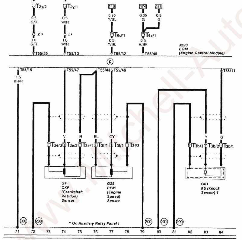
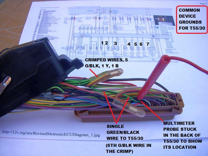
30/55- Ground for ECU and ECU sensors – BK/V – Including G61, G66, G69, F96, G62, G42 and the Coding Card
31/55- Fuel consumption signal for trip computer – BR/BK or BL or BL/BK
32/55-Output to Trip Computer Boost Pressure Gauge - ??
33/55 - Ground for N75 Waste Gate Frequency Valve - - G/Y - also known as the charge pressure control actuating valve - lets the ECU control the boost - by dumping excess boost through the waste gate
34/55 - Output control signal to Fuel Injector No. 3 - N32 – BR/G
35/55 - Output control signal to Fuel Injector No. 4 - N33 - BR/W
36/55 - Output control signal to Fuel Injector No. 1 - N30 – BR/BK
37/55-Switched +12V for all 5 Fuel injectors (N30-N83) and MAF (G70)- BL/BK - Provides ignition-on power to injectors and MAF during starting conditions and then power to the MAF for the hot-wire burn-off after the ignition is turned off all via a "Holding Relay" in the ECU. (Main power to the injectors and MAF comes through the J17 FP relay via pin 87A and Fuse S28 after the engine is started).
38/55-T6ag Coding plug -Pin 1-BR/BL
39/55-T6ag Coding plug- Pin 2- W/BK
40/55-OUTput from G28 Engine Speed Sensor – V/V - Also connected to Ch.27 in the A/C head (you can read out RPM in the A/C head) Link to Climate Control Diagnostics
41/55-Signal from A/C control module –BK/Y - signal used by ECU to increase idle speed through ISV control when A/C compressor is activated (actually just maintains the idle speed when the extra load from A/C compressor is added to the system during idle)
42/55 – Communication with Autotrans computer and therefore not applicable to S2 or RS2
43/55 - Not used (*might* be Autotrans related??)
44/55 - Input from G42 Intake Air Temperature (IAT) Sensor – BK/Y - the ECU uses this signal to dial back timing (and power) to prevent pinging if the intake air temp is too high
45/55 - Input from G62 Engine Coolant Temperature Sensor – R/G - the one at the back of the head that the ABY/ADU ECU uses to figure out if the A/F should be enriched because the engine is cold.
46/55- BL/W – Connection to the “R” pin on the F76 Multifunction Temperature Switch to flag an overheating condition so the ECU knows to back off the boost, etc. to help get the coolant temps down
47/55- Input from G4 Crankshaft Position Sensor – R/R - used by the ECU to control ignition and fuel injector timing
48/55- Combined ground through ECU for G4 crankshaft position sensor and the G28 engine speed sensor - V and G wires from G4 and G28
49/55-Input from G28 Engine Speed sensor BL/BL -allows the ECU to figure out the engine RPMs and make the required decisions
50/55- Road Speed signal input from the Instrument Cluster Speedometer -G21-W/BL-signal - also goes to Automatic Climate Control Head Channel 17 - which you can read out speed as well, the Servotronic Control Module, the cruise control module and the UrS4 lockable rear differential controller (under the rear seat so it can dis-engage the rear diff lock at 15 mph (25 kph)). More details about the white/blue wire and where its branches go is available HERE. More info about the G22 Vehicle Speed Sensor (VSS) 012409191D and G21 Speeodmeter . The ECU uses this road speed signal to know that the vehicle is moving so that when throttle position switch (Pin 52/55) is indicating closed but the vehicle is moving, the ECU can shut down the injectors to save fuel while coasting. Conversely, if the road speed is zero and throttle is closed, the ECU knows that this is the idle condition and it keeps the injectors active.
51/55- Not used for standard transmission cars - relates to kick-down shift point for automatic trans cars. Third digit in VAG-com measuring block 005. Normally "0" until kick-down with Autotrans when it goes to "1". (Thanks to "MG" on the S2 forum for this info)
52/55 - Signal from F60 Idle Switch -G/V- a microswitch inside the G69 throttle potentiometer that tells the ECU that the throttle is closed. With this signal and the Road speed signal on Pin 50/55, the ECU knows that the car is either idling at a stop or coasting throttle closed and decides how to handle the injectors accordingly.
53/55 - Input from G69 Throttle valve potentiometer – G/BL the potentiometer on the throttle body that tells the ECU the degree to which the throttle body is open, which helps it compute "load".
54/55- Not used for standard transmission cars - relates to automatic trans cars
55/55- Output to Data Link connector "K" for diagnostics - G/R or G/G
The PN of the ABY S2 ECU was 895907551A. The replacement was 895997551X
As twoqu (Robin) said: "Don't forget that there was immo versions of both ABY (551B) and ADU (551C). The part numbers with X in them represent exchange items."
Thanks for that Robin. It gave me the leads I needed to start tracking the PNs back to the beginning.
8A0907551B was replaced by 8A0997551X on 01/08/2002
8A0907551A was dropped and replaced by 895907551A (for the ABY) - no date noted
895907551A was replaced by 895997551X on 01/11/2002
895997551B (for the ABY) was replaced by 895997551AX on 01/05/2002
The RS2 ADU ECU PN shows up now as 8A0997551X or 8A0997551BX but was originally a 8A0907551C which was replaced the 8A0997551X on 01/05/2002
In playing with those PNs, I found this 8A0907551C photo in a pricy ebay.de RS2 ECU advert:
http://www.ebay.de/itm/Audi-Steuerge...-/262293472974
The main difference between the ABY and ADU ECUs are the chip sets and the ABY has a 250 kPa (2.5 Bar) Bosch MAP sensor and the ADU has a 300 kPa (3.0 Bar) Bosch MAP sensor. There is also a change in the resistance of the R201 resistor on one of the Boards that extends the electrical range of the RS2's G70 MAF sensor.
The ABY/ADU ECU connector has 55 pin positions. The pins are arranged in three rows. The longest row has 19 pins, Pins 1 through 19. Pin 1 is nearest the metal release lever on the harness connector. The middle row is Pins 20 through 37, with Pin 20 nearest the metal release lever. The last row is Pins 38 through 55 with Pin 38 nearest the metal release lever. Not all pins are used.
The following are the Pins and their assignment. Wire colours are from Paul Nugent’s S2Central.net website. Note underlined Hyperlinks to additional information about the device in question.
The Letter/Number, e.g. N71, are for the devices that are either being controlled or are sending a signal to the ECU. The Letter/Letter code is the wire colour code. Not all pins are used - especially on the standard transmission cars.
Wire Colour Codes used in the pin-out list below:
BK = Black
BL = blue
BR = Brown
CL = Clear
G = green
GY = gray
LT G = Light green
OR = orange
R= red
V = Violet aka “lilac”
W = white
Y = Yellow
Examples:
W/V = white with a violet stripe
R/BK = red with a black stripe
Pin - Assignment - Device Code - wire colour - Comment (if any)
1/55 - Output to Power Output Stage - N122- G/W- for Coil No. 1 (N122 Pin 4/4) Detailed POS wiring info including the corrections to the factory schematics
2/55 - Output to Power Output Stage - N122 – V - for Coil No. 2 (N122 Pin 3/4)
3/55 - ECU-controlled ground for the J17 Fuel Pump Relay - BR/G - ECU triggers the relay after it gets the G40 cam position sensor signal by pulling the J17 fuel pump relay to ground through pin 3.
4/55 - ECU-controlled ground for the N71 Idle Air Control Valve (aka Idle Stabilization Valve (ISV)) – G/BK - the ISV is used to control the idle, e.g. when the air conditioning compressor comes on or coming to a stop.
5/55 - ECU-controlled ground for the N80 Evaporative Emissions Control Valve – W - Controls the evaporative emissions frequency valve - N80 - to cycle evaporated fuel vapours back in to the engine (NOTE: Bentley shows this as T55/3 on page X57 - presumably in error) VAG143 has it as N80.
6/55-Connection to A/C Control Head -E87- G/BK - Used to shut off A/C for up to 12 seconds when throttle is opened rapidly at speeds under 7 kph and shut off A/C for up to 3 seconds when in first gear and throttle position is at 65 degrees or more (full load) Ref: VAG143.
7/55-Input from G70 Mass Air Flow (MAF) Sensor - BK/W - the MAF allows the ECU to know how much air (by mass) is heading to the cylinders so it can adjust the fuel, boost and timing to suit the conditions
8/55- Input from G40 Cam Position Hall Effects Sender – G - signal wire - Note lack of signal = Blink code 2113 and the engine will not start. J17 fuel pump relay is not triggered.
9/55 - Input from F96 Barometric pressure/altitude sensor – GY - provides a signal to the ECU to help control boost at higher altitudes - between 1000 and 4000 meters - prevents the turbo from spinning over 155000 rpm.
10/55- One of the Grounds for the ECU -BR/Y
11/55 -Input from G61 Knock Sensor No. 1 = W - for cylinders No. 1, 2 and 3
12/55- Power Supply (+5V) out to Hall sender - G40; G69 Throttle Potentiomenter and Altitude Sensor (F96) - R/BK -
13/55- Output to Data Link connector "L" for diagnostics - G/GY or W/R
14/55-Ground for Fuel Injectors (N30-83)- BR/R - ground on intake manifold
15/55-Not Used
16/55 - Output control signal to Fuel Injector No. 5 - N83 – BR/R
17/55- Output control signal to Fuel Injector No. 2 - N31 – BR/BL
18/55- Constant power supply to ECU J220 - R/W- from power terminal 30 (+12V) Fuse S27 (20A) – This constant power also feeds the Holding Relay for its work during start-up and shut-down.
19/55- Ground from the ECU for various ECU controlled devices - BR/Y - to intake manifold
20/55 - Output to Power Output Stage - N127 – R/BK - for Coil No. 4 (Note - some early versions of the Bentley have this as Coil No. 5 - but this is wrong, it is 4 - check it yourself) - VAG143 has it correct.(N127 connector Pin 4/4)
21/55 - Output to Power Output Stage - N127 – G/G - for Coil No. 5 (Note - some early versions of the Bentley have this as Coil No. 4 - but this is wrong, it is 5 - check it yourself)- VAG143 has it correct. (N127 connector Pin 3/4)
22/55 - Data Link Connector – GY/BR - linked to Check engine light (Malfunction indicator lamp) - also used in the blink code check.
23/55 - Output to Power Output Stage - N122- BK/BL signal for Cyl #3 Ignition coil (N122 connector Pin 1/4)
24/55- Power Ground for "actuators" other than injectors - Not found in Bentley,BR/R, ground to intake manifold
25/55- Mass Air Flow (MAF) Sensor (aka - hot-wire air volume meter) - G70 - BL/V- Burn off signal from ECU - every time the engine is switched off, the hot wire is heated to 1000 deg C for one second to keep it clean
26/55- G70 MAF – SW/G or W/G - "Reference voltage, earth (ground) in"
27/55- Switched Power to ECU from power (+12V) – Fuse S32 – BK/BK
28/55- Input from G39 Heated Oxygen (O2) Sensor - G/G- This is the single black wire coming out of the O2 sensor to a single spade connector in the harness at the connector rack. The two white O2 wires are for the heater and are not run through the ECU.
29/55-Input from G66 Knock Sensor No. 2 - G/G for cylinders No. 4 and 5
30/55- Ground for ECU and ECU sensors – BK/V – Including G61, G66, G69, F96, G62, G42 and the Coding Card
31/55- Fuel consumption signal for trip computer – BR/BK or BL or BL/BK
32/55-Output to Trip Computer Boost Pressure Gauge - ??
33/55 - Ground for N75 Waste Gate Frequency Valve - - G/Y - also known as the charge pressure control actuating valve - lets the ECU control the boost - by dumping excess boost through the waste gate
34/55 - Output control signal to Fuel Injector No. 3 - N32 – BR/G
35/55 - Output control signal to Fuel Injector No. 4 - N33 - BR/W
36/55 - Output control signal to Fuel Injector No. 1 - N30 – BR/BK
37/55-Switched +12V for all 5 Fuel injectors (N30-N83) and MAF (G70)- BL/BK - Provides ignition-on power to injectors and MAF during starting conditions and then power to the MAF for the hot-wire burn-off after the ignition is turned off all via a "Holding Relay" in the ECU. (Main power to the injectors and MAF comes through the J17 FP relay via pin 87A and Fuse S28 after the engine is started).
38/55-T6ag Coding plug -Pin 1-BR/BL
39/55-T6ag Coding plug- Pin 2- W/BK
40/55-OUTput from G28 Engine Speed Sensor – V/V - Also connected to Ch.27 in the A/C head (you can read out RPM in the A/C head) Link to Climate Control Diagnostics
41/55-Signal from A/C control module –BK/Y - signal used by ECU to increase idle speed through ISV control when A/C compressor is activated (actually just maintains the idle speed when the extra load from A/C compressor is added to the system during idle)
42/55 – Communication with Autotrans computer and therefore not applicable to S2 or RS2
43/55 - Not used (*might* be Autotrans related??)
44/55 - Input from G42 Intake Air Temperature (IAT) Sensor – BK/Y - the ECU uses this signal to dial back timing (and power) to prevent pinging if the intake air temp is too high
45/55 - Input from G62 Engine Coolant Temperature Sensor – R/G - the one at the back of the head that the ABY/ADU ECU uses to figure out if the A/F should be enriched because the engine is cold.
46/55- BL/W – Connection to the “R” pin on the F76 Multifunction Temperature Switch to flag an overheating condition so the ECU knows to back off the boost, etc. to help get the coolant temps down
47/55- Input from G4 Crankshaft Position Sensor – R/R - used by the ECU to control ignition and fuel injector timing
48/55- Combined ground through ECU for G4 crankshaft position sensor and the G28 engine speed sensor - V and G wires from G4 and G28
49/55-Input from G28 Engine Speed sensor BL/BL -allows the ECU to figure out the engine RPMs and make the required decisions
50/55- Road Speed signal input from the Instrument Cluster Speedometer -G21-W/BL-signal - also goes to Automatic Climate Control Head Channel 17 - which you can read out speed as well, the Servotronic Control Module, the cruise control module and the UrS4 lockable rear differential controller (under the rear seat so it can dis-engage the rear diff lock at 15 mph (25 kph)). More details about the white/blue wire and where its branches go is available HERE. More info about the G22 Vehicle Speed Sensor (VSS) 012409191D and G21 Speeodmeter . The ECU uses this road speed signal to know that the vehicle is moving so that when throttle position switch (Pin 52/55) is indicating closed but the vehicle is moving, the ECU can shut down the injectors to save fuel while coasting. Conversely, if the road speed is zero and throttle is closed, the ECU knows that this is the idle condition and it keeps the injectors active.
51/55- Not used for standard transmission cars - relates to kick-down shift point for automatic trans cars. Third digit in VAG-com measuring block 005. Normally "0" until kick-down with Autotrans when it goes to "1". (Thanks to "MG" on the S2 forum for this info)
52/55 - Signal from F60 Idle Switch -G/V- a microswitch inside the G69 throttle potentiometer that tells the ECU that the throttle is closed. With this signal and the Road speed signal on Pin 50/55, the ECU knows that the car is either idling at a stop or coasting throttle closed and decides how to handle the injectors accordingly.
53/55 - Input from G69 Throttle valve potentiometer – G/BL the potentiometer on the throttle body that tells the ECU the degree to which the throttle body is open, which helps it compute "load".
54/55- Not used for standard transmission cars - relates to automatic trans cars
55/55- Output to Data Link connector "K" for diagnostics - G/R or G/G


 But just for saving myself: you really can't say what's inside the chip by just looking the stickers.


Comment