
 Tweet
Tweet
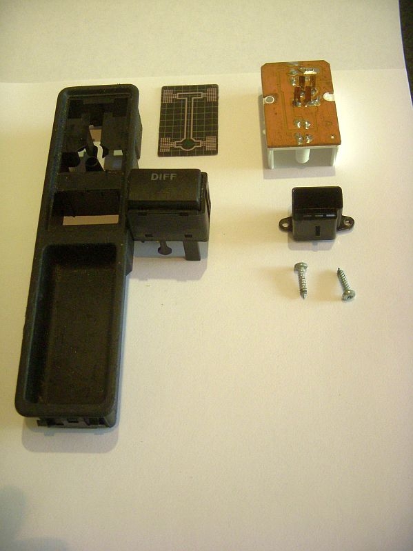
The diff lock switch bezel in my 94 S4 V8 avant was not in the best of shape. I happended to find a good one from a 93 100q at a breaking yard during the week and I decided to buy it and install it in the 94 S4 (looks much better). As I did so, I got curious about the components inside the switch and I decided to see how easy it was to take the old one apart. Pretty easy if you go slow. The diff lock bezel map is just glued into the housing. You can start it from the back and then use something thin from the upper side to work it off slowly (don't force it, be gentle, but firm).
The actual diff lock switch has four small tabs that lock it into the housing - push from the top and pull from the back.
Here is what the diff lock switch looks like in Phase 1 of the parts breakdown:
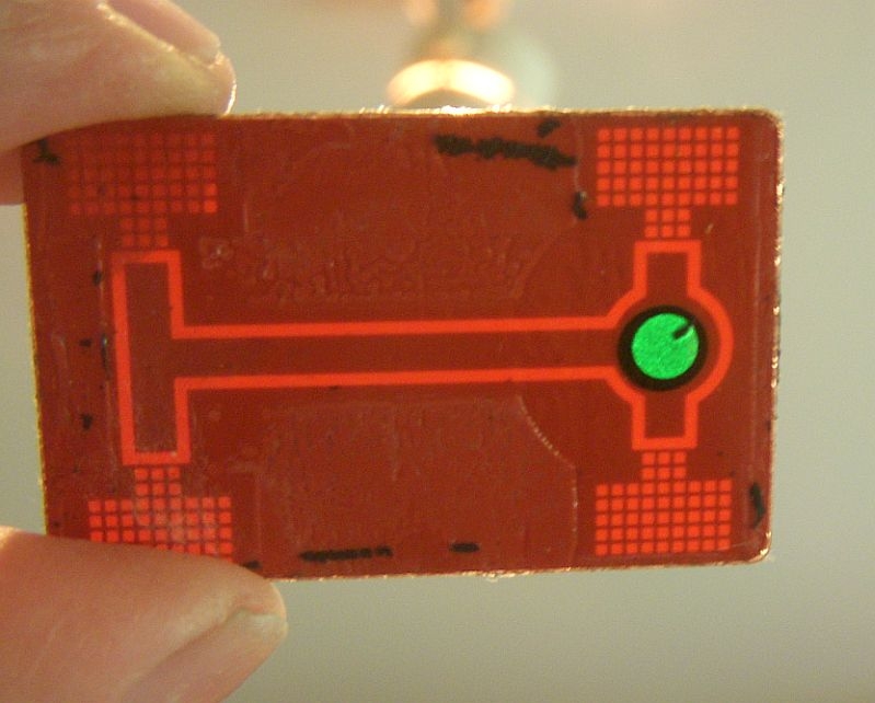
The second photo shows the black speck of crud that was bugging me yesterday. It's some kind of stray material that got stuck under the spray on glue that they must have used at the factory (and apparently Hans and Franz didn't catch it in quality control).
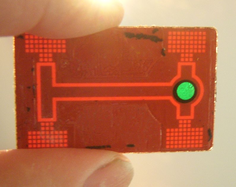
Third photo shows the crud removed (gentle removal with the tip of a kitchen paring knife)
Not one to let obsession for detail stand in the way of leisure time, I then decided to pull things apart further to find out what was really going on inside the switch assembly.
First thing was to review what the electrical schematics say about the diff lock switch. This diagram was taken from my Rear Diff Lock 101 post
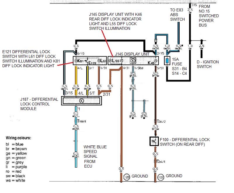
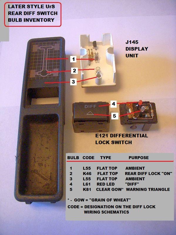
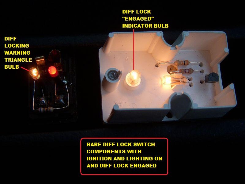
So here is the resulting bulb inventory: 4 incandescents and one LED:
Now a series of shots showing what you see from the top and what is going on below when you get in and start your rear diff lock equipped UrS (S2, RS2, UrS4 and 95 UrS6).
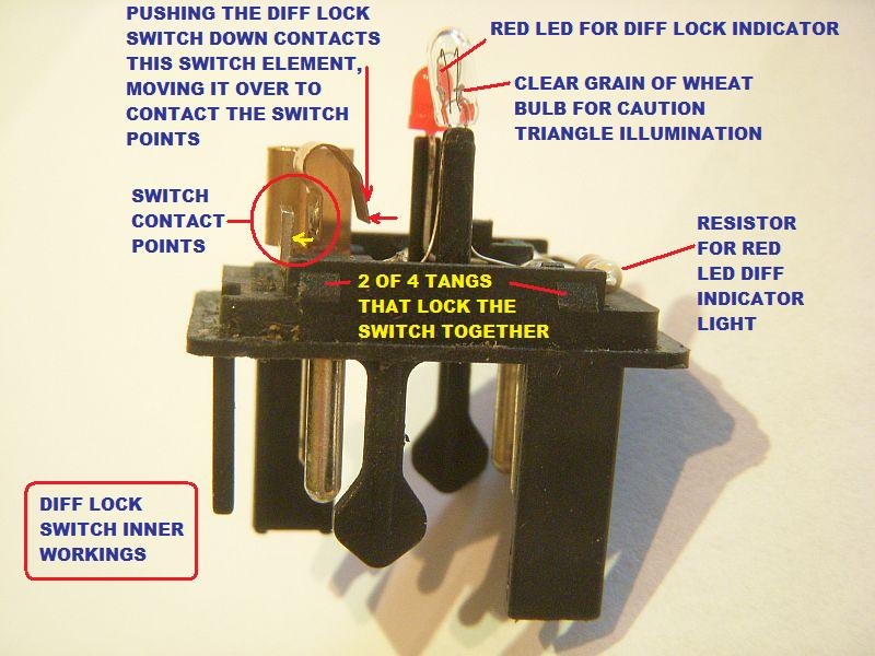
First a shot of the actual diff lock switch. The interesting part (to me) is the upper "Diff" switch is just a spring loaded plunger that you push down and then release (not a toggle on/toggle off switch per se). As you push the "DIFF" plunger down, a tang on the inner side of the plunger moves a copper conductor spring over, resulting in a temporary completion of the Diff lock circuit which then activates the Diff lock and the Diff lock indicator and warning lights.
When you first get in the car, the Diff lock switch will be completely dark. When you start the car, the red LED "DIFF" indictor is turned on, presumably so you can find it in the dark (??). It is the only lamp that is on. I presume that an LED was chosen for the illumination because it is on all the time the engine is on.

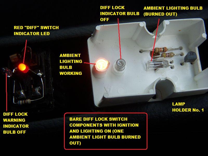
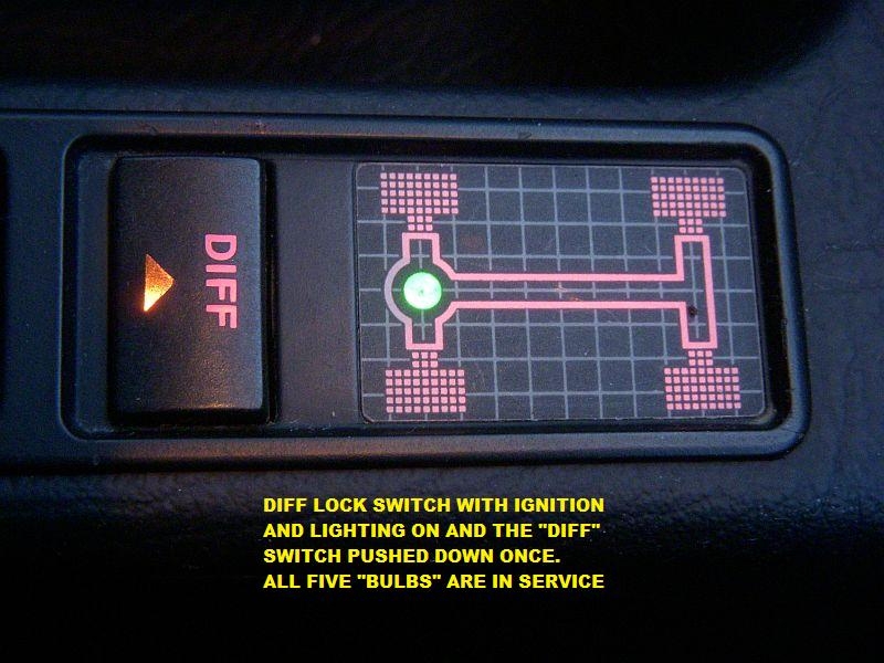
When you turn the headlights (or just the Park lights) on, the ambient lighting bulbs come on:

This is what is going on underneath the indicator map. (NOTE: I had to use two different lamp holders to show that there are two ambient light bulbs. In my case, each of the two lamp holders had one ambient lighting bulb burned out).
Lamp Holder 1:
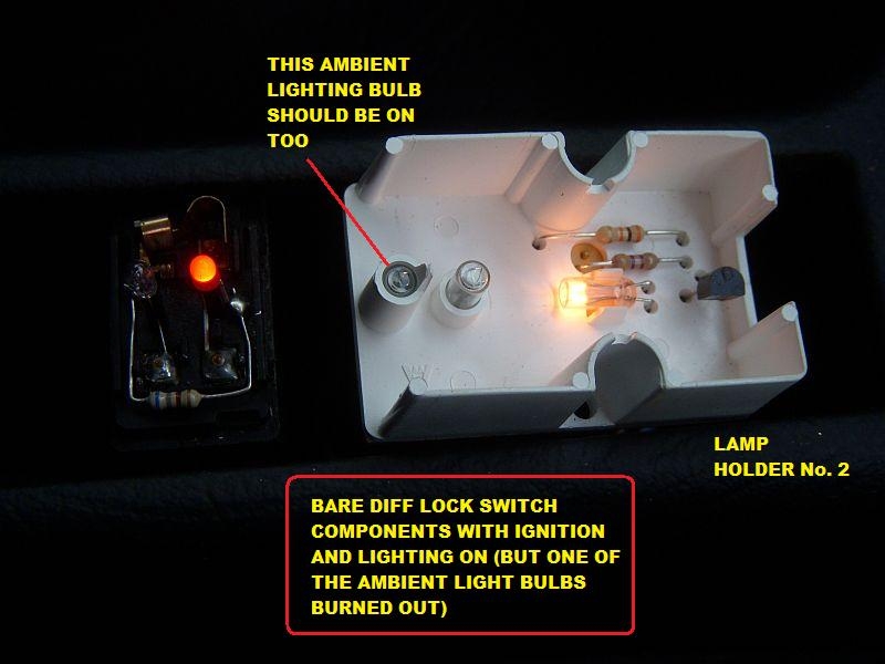
Lamp Holder 2:
Finally, when you push the DIFF lock switch plunger down, the switch contact is temporarily made and the diff lock control module locks the rear diff and powers the Diff lock engaged and Diff lock warning lights:
And underneath, using Lamp Holder 2 with its burned out ambient light bulb, to show the diff lock indicator and warning bulbs being powered.
Now to try EdiGreg's Plastidip trick on the switch bezel and seek out replacement bulbs for the burned out ambient bulbs.
The actual diff lock switch has four small tabs that lock it into the housing - push from the top and pull from the back.
Here is what the diff lock switch looks like in Phase 1 of the parts breakdown:
The second photo shows the black speck of crud that was bugging me yesterday. It's some kind of stray material that got stuck under the spray on glue that they must have used at the factory (and apparently Hans and Franz didn't catch it in quality control).
Third photo shows the crud removed (gentle removal with the tip of a kitchen paring knife)
Not one to let obsession for detail stand in the way of leisure time, I then decided to pull things apart further to find out what was really going on inside the switch assembly.
First thing was to review what the electrical schematics say about the diff lock switch. This diagram was taken from my Rear Diff Lock 101 post
So here is the resulting bulb inventory: 4 incandescents and one LED:
Now a series of shots showing what you see from the top and what is going on below when you get in and start your rear diff lock equipped UrS (S2, RS2, UrS4 and 95 UrS6).
First a shot of the actual diff lock switch. The interesting part (to me) is the upper "Diff" switch is just a spring loaded plunger that you push down and then release (not a toggle on/toggle off switch per se). As you push the "DIFF" plunger down, a tang on the inner side of the plunger moves a copper conductor spring over, resulting in a temporary completion of the Diff lock circuit which then activates the Diff lock and the Diff lock indicator and warning lights.
When you first get in the car, the Diff lock switch will be completely dark. When you start the car, the red LED "DIFF" indictor is turned on, presumably so you can find it in the dark (??). It is the only lamp that is on. I presume that an LED was chosen for the illumination because it is on all the time the engine is on.
When you turn the headlights (or just the Park lights) on, the ambient lighting bulbs come on:
This is what is going on underneath the indicator map. (NOTE: I had to use two different lamp holders to show that there are two ambient light bulbs. In my case, each of the two lamp holders had one ambient lighting bulb burned out).
Lamp Holder 1:
Lamp Holder 2:
Finally, when you push the DIFF lock switch plunger down, the switch contact is temporarily made and the diff lock control module locks the rear diff and powers the Diff lock engaged and Diff lock warning lights:
And underneath, using Lamp Holder 2 with its burned out ambient light bulb, to show the diff lock indicator and warning bulbs being powered.
Now to try EdiGreg's Plastidip trick on the switch bezel and seek out replacement bulbs for the burned out ambient bulbs.

 Never ceases to amaze me such are his talents
 !
!


Comment