You can change the style the forum displays by selecting your preferred style at the bottom left of the site.
We have made an enhancement so that old threads should now link from search results to the correct thread. This is not yet in place for single post links
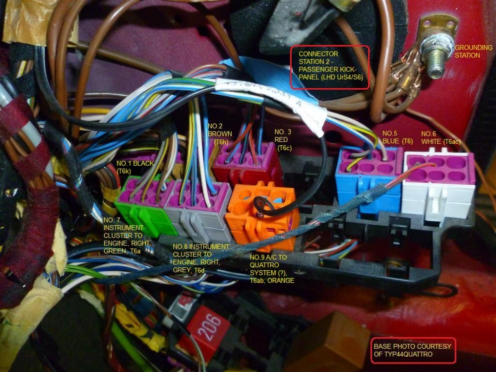
I had to go to my Connector Stn 2 post to confirm that the T6a is green and the T6c is red and its the T6c that carries the speedometer signal and T6a the tachometer signal.
Updated the 2007 version of my AAN pin-out in Post 1 in this thread to the current version I have at my home forum, quattroworld. With photos and hyperlinks to the connected devices, etc. etc.
While wire colours might not cross to the ABY and ADU the pins are the same and info about the connected devices applies equally well.
RS2'd 93 UrS4 5 spd sedan
94 UrS4 V8 6 spd manual avant
Does anyone know what type of signal pin 41 gets when ac is on?
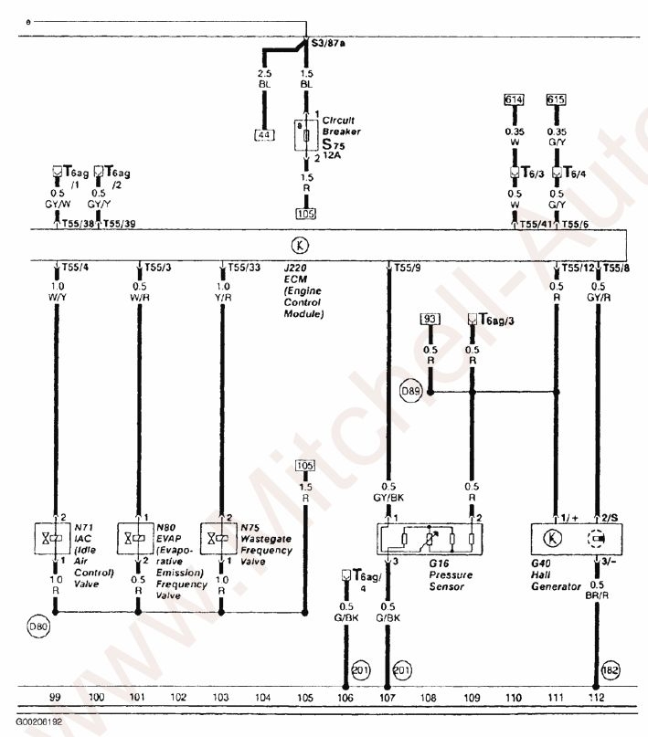
41/55-Signal from A/C control module -W/W - signal used by ECU to increase idle speed through ISV control when A/C compressor is activated (actually just maintains the idle speed when the extra load from A/C compressor is added to the system during idle)
Does anyone know what type of signal pin 41 gets when ac is on?
41/55-Signal from A/C control module -W/W - signal used by ECU to increase idle speed through ISV control when A/C compressor is activated (actually just maintains the idle speed when the extra load from A/C compressor is added to the system during idle)
My guess is just a 5V signal (instead of a 0 V signal). However, you can find out for yourself, if you want (see below)
In addition to the T55/41 white/white wire connection between the ECU and the A/C control head you've quoted above, there is also the connection at Pin T55/6:
6/55-Connection to A/C Control Head -E87- G/Y - Used to shut off A/C for up to 12 seconds when throttle is opened rapidly at speeds under 7 kph and shut off A/C for up to 3 seconds when in first gear and throttle position is at 65 degrees or more (full load) Ref: VAG143.
(Bonus reference -A/C control head diagnostics: http://www.audiworld.com/tech/int5.shtml)
These two connections show up in this ECU pin-out diagram, meandering off to another wiring diagram from lines [110] and [111] here to lines [614] and [615] in the other diagram via some six pin connector "T6" somewhere.
Well, it turns out, I've previously partially documented some of the six pin connectors in Connector Station 2 (passenger side front kick panel). "T6" is the blue connector on the connector rack. The wire colours of interest are the white/white wire and the green/yellow wire. Because of the exposed end of the pin or the fact that T6 is two parts, you could use a digital multimeter to probe the voltage changes in those two pins, T6/3 and T6/4.
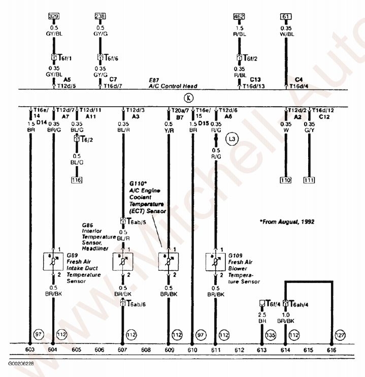
After Connector Stn 2, the white/white and green/yellow wires head over to the A/C control unit where they enter the A/C control unit on pins T12d/2 and T16d/12, respectively. You could always probe for voltages there as well.
In this diagram, we pick up the [110]/[614] and [111]/[615] connections:
Thanks very much for the guide, its proven useful to me to say the least.
However, since my wiring harness has none of the plugs that would be used to interrogate the ecu via blink codes, can anyone advise the correct ecu pin numbers id need to use in order to allow reading of the blink codes and the procedure to perform it?
Also I dont have an engine check light fitted, my plan is to incorporate one into a spare position on the rear of the instrument pod if possible, so I also need to know which ecu pins id need to allow connection of that item if anyone can help.
Thanks very much for the guide, its proven useful to me to say the least. ...Also I dont have an engine check light fitted, my plan is to incorporate one into a spare position on the rear of the instrument pod if possible, so I also need to know which ecu pins id need to allow connection of that item if anyone can help.
The info is there in my first post in this thread.
Pins 13, 22 and 55. Have another read of that post.
Thanks for the reply, some help but not quite what I was after.
Looking at the diagram, it appears pins 13 and 55 would be jumpered to set the ecu into blink mode? Or would that do some damage?
The mil light on pin22 shows only a partial circuit, which is why im a tad confused.
Assuming a bulb of particular wattage say 1.5 watts is connected to that pin 22, is it the case that its grounded or fed 12 volts?
The diagrams not clear at all on those points which is where my problem lies.
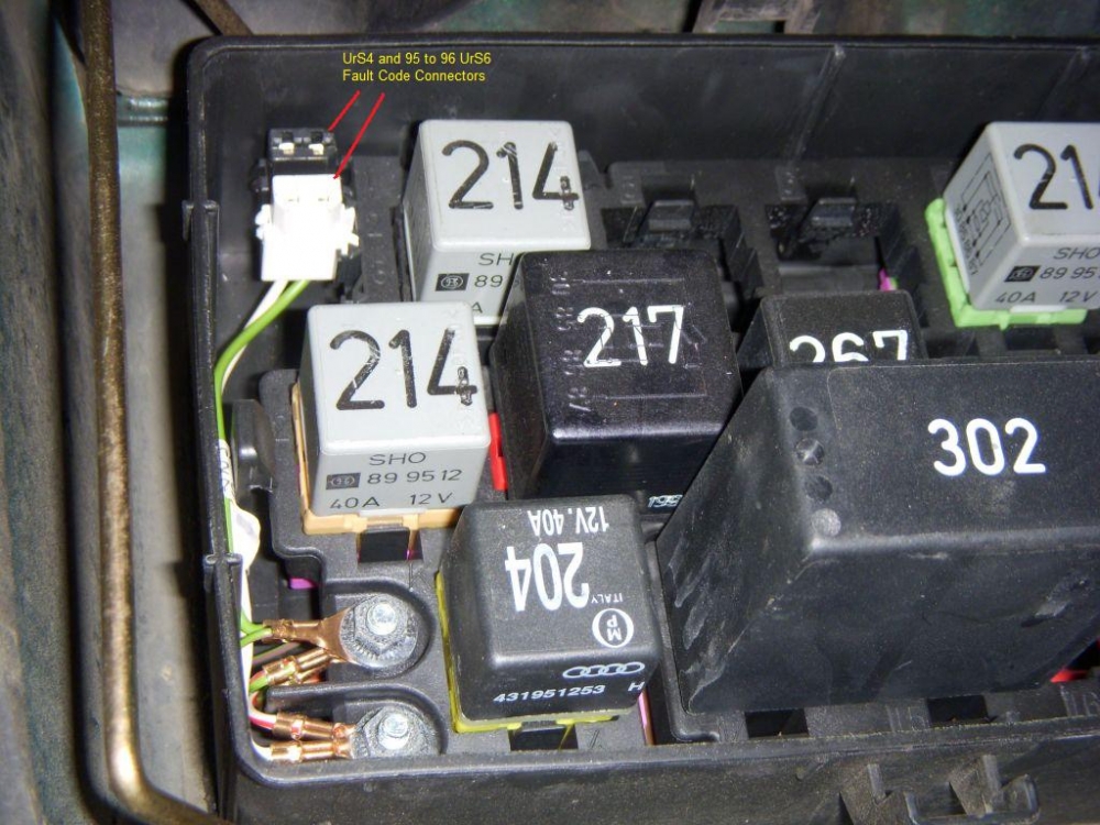
You will want to find the black and white connectors from a wrecked car an hook them up so you can access the codes.
Please read that post (again, if necessary).
No use triggering anything unless you have a MIL light hooked up. Paul Nugent has posted on how to set up a MIL light.
If you can't find that, down load this 113 page UrS4 wiring diagram and look at pages 47/113, 48/113 and 56/113 regarding Pins T55/13, T55/22 and T55/55 and the MIL light.
But even better is set yourself up with those black and white connectors and buy a 2x2 adapter cable and this scanning tool (very reasonably priced) (off ebay uk)
Thanks so much for that link to 12v.0rg, just the info i was after.
It appears fuse s14 heads to current track 192/3, wire colour is black/blue comes out in track 70 through the mil light and splits off the dlc before hitting pin22.
It answers the question of whether its fed voltage or grounded for me anyway!
I had already read the post on using the scan tool, very usefull idea, I do already have a similar one, the U280 so dunno if thatll work, but if not ive already got a much more comprehensive tool which ive found useful : https://www.matcotools.com/catalog/p...R-129-PREMIUM/
Checking my wiring harness vs the diagram I find the K line wire is green and black instead of green and red, its on the right pin tho.
L line is correct pin and colours.
I have found that pin 22 for the MIL light isnt installed in the T55 connector, so ill have to install one myself, no issue, only thing thats nagging is will the software/hardware in the ecu be coded to run an MIL.....
Fun.
Qucik question: Has anyone got the part numbers for the diagnostic plugs? I may be able to order them and pin them myself instead of hunting for them on the net.
Qucik question: Has anyone got the part numbers for the diagnostic plugs? I may be able to order them and pin them myself instead of hunting for them on the net. Thanks.
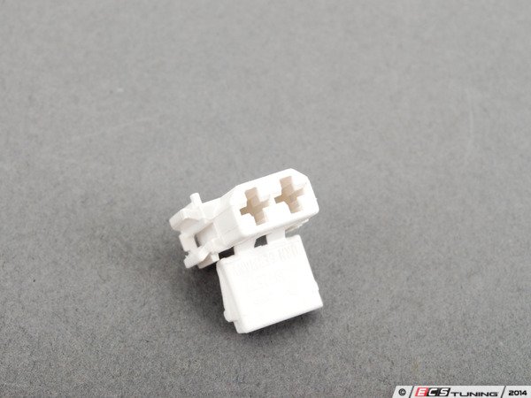
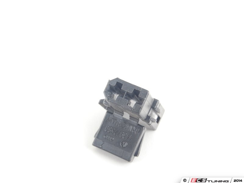
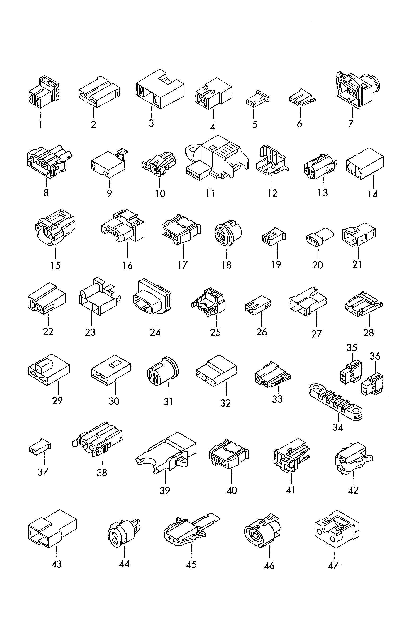
My suggestion was to find them in an older Audi in a breaker's yard. However, I surprised myself and was able to find the 2 pin diagnostic plugs in the non-model specific Electrical section of ETKA (I chose 1993 for the year). Items 35 and 36:
We process personal data about users of our site, through the use of cookies and other technologies, to deliver our services, personalize advertising, and to analyze site activity. We may share certain information about our users with our advertising and analytics partners. For additional details, refer to our Privacy Policy.
By clicking "I AGREE" below, you agree to our Privacy Policy and our personal data processing and cookie practices as described therein. You also acknowledge that this forum may be hosted outside your country and you consent to the collection, storage, and processing of your data in the country where this forum is hosted.

 Tweet
Tweet


Comment