
 Tweet
Tweet
A complete retrofit of an ATD. Other threads discuss which models got them and which didn't.
This will hopefully show you how to fit one, even if your car doesn't have the wiring and required connector in the loom behind the clocks. Part numbers and so on will be listed at the end of this post.
This ATD retrofit was done to Paulgo's pearl white 3B S2 Coupe.
As mentioned before, it seems some 3B models have the wiring and connector behind the clocks, (Pete's (acidburn) 3B has the wiring and connector, but Paulgo's 3B had nothing.
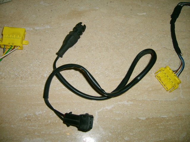
If you have the connector behind there, it'll be either a yellow 5 pin connector, or a black 5 pin connector. There's no mistaking it, as it's to only loose connector behind the clocks. When you order that connector (if you need to) from a dealer it'll be black. No difference between them apart from colour.
First job was the sensor. It's normally located deep down below the nearside headlamp, attached to a bracket on the front bodywork.
A sensor was obtained from vagparts, but for whatever reason, the bracket that it attaches to wasn't there either and it's something we overlooked too.
It was decided that we would just attach it to the bodywork with a stout cable tie.

It doesn't matter which of the two wires that come off the sensor you use to go to either the connector behind the clocks, or to an earth. Both can be used for either job.
A suitable earth point was located on the nearside front strut tower where something in the past had been earthed there. A ring tag was crimped on the end of the standard yellow cabling and secured to this point.

The other wire was then extended with some 16awg cable using solder and some heatshrink, then routed round the strut tower, along the bulk head below the strutbrace and onto a grommet that passed through the bulkhead just below the brake fluid reservoir and just above the rack.

This grommet emerged into the area under the drivers parcel shelf, that awful spaghetti wiring hell that is the bottom of the fuse box and the aux relay plate (nice fine mess Audi)
Not a bad position for it to come through as it's not kicking the arse of the rear of the clocks.
Ok, as said, Paulgo's car had nothing. Just before he bought his S2 he had a Coupe quattro 20v and had fitted the on board computer to it. He bought a complete S2 dash loom so he could steal the little wiring loom that job needed. Luckily this loom contained the yellow 5 pin connector we now needed.
What ever model this loom came from, it hadn't had the ATD fitted as the wiring from the connector was just blanked off and buried in the loom.
We traced the wiring from the connector as far as we could and snipped all 5 wires from the loom.
All was needed to do then was to splice all 5 wires into the various places they needed to go.

You'll be splicing into wiring coming from the yellow 26 pin connector and the blue 26 pin connector that plug into the rear of the clocks. You'll see the yellow or black 5 pin and both 26 pin connectors have the pin numbers on them.
The yellow and blue connector need opening to determine the pin numbers, just pry apart the top of them and slide the internals out of the side. No fear of the pins coming out and getting mixed as they are clipped into place on the connector.
You need to splice as follows. Note, an earth will need to be run, we earthed into a cable Paul had already conveniently run up past the clocks for use on his boost gauge.
1 = Vehicle Speed signal - to pin 20 (brown/red) [blue 26-pin connector]
2 = Temperature sensor - to sensor wire you have routed from the engine bay.
3 = Earth (see above)
4 = Illumination - to pin 5 (grey/blue) [yellow 26-pin connector]
5* = +12v - to pin 16 (black/blue) [blue 26-pin connector]
All splicing was done using solder, heatshrink and then some insulating tape covering it. We just spliced into the wires a couple of inches back from where they entered their respective connectors.
As noted by Pete (acidburn) while has been looking at doing this, he has this 5 pin connector in the loom already, but it's missing the +12v to it. No problem, just do as above where it's marked *.
With that done, make sure non of your wiring is wrapped around any area of the steering column, this once happened to my old Coupe after having an immobiliser fitted. The numpties had coiled wire around the steering column and the car stopped steering mid corner. Not good. You can now plug in your ATD to the 5 pin plug, turn on the ignition and it should now tell you the outside temp. If it doesn't light up and show, don't immediately think your work is bad. The bulb may have gone inside as it's on all the time the ignition is. Open it up by removing the tape around it's circumference and removing the two screws. If the lamp inside isn't lit with the ignition on, it's more than likely dead. This is assuming of course that you've managed to buy a secondhand display. If it's new and still doesn't light, recheck your wiring.
Time to fit your ATD to the rear of the clocks. It's screwed into position after you've lifted up and moved out of the way, the bottom part of the lamp legend card. You'll see what I mean. Refit your clocks and sit back and now complain how cold it is.

Pauls ATD display was secondhand and as such the bulb inside was dead. It's an easy job to replace with either a new bulb or a small 3mm superbright LED. Beauty of the LED is that it'll last for an age. A bulb won't. Down point of an LED is that it'll make a small bright spot. If that doesn't bother you then all's fine, if it does does rub over the top of the LED with some sandpaper, don't go mad though, you just need to scuff it up a bit so the light is more diffused.
A "cj70m" 3mm miniature LED from maplins, a bit of soldering and you'll have illumination at night again.
A tip though, don't completely unsolder the old bulb, just snip it off and leave it's old legs sticking up,

trim down the LED's legs to the correct length and resolder to the old.

Two reasons for doing this, the holes on the pcb are tiny, and I mean tiny as you can see, you'll have to enlarge then them to insert new LED's legs and that leaves hardly any track on both the top and bottom of the pcb, second is the longer you faff around with a soldering iron on the pcb, the more likely you are the heat damage the components on it.
Remember to determine the correct orientation of the LED (cathode and anode), it'll only work one way round. To do this. reconnect the ATD up and turn the ignition on. Briefly touch the new LED to the old bulbs legs sticking up from the board. If it doesn't light, turn it 180° and briefly touch again. Once you know which way around it goes, make note of it and then go ahead and solder it on. Be quick, don't hang around for to long with a soldering iron. The components on the board are small and don't like high temperatures.
Reattach the ATD to the connector, turn on the ignition and the LED should now be lit.

Refit the LCD screen and then test again.

Refit it back onto the clocks and refit the clocks. Sit back and enjoy.

Jas..
This will hopefully show you how to fit one, even if your car doesn't have the wiring and required connector in the loom behind the clocks. Part numbers and so on will be listed at the end of this post.
This ATD retrofit was done to Paulgo's pearl white 3B S2 Coupe.
As mentioned before, it seems some 3B models have the wiring and connector behind the clocks, (Pete's (acidburn) 3B has the wiring and connector, but Paulgo's 3B had nothing.
If you have the connector behind there, it'll be either a yellow 5 pin connector, or a black 5 pin connector. There's no mistaking it, as it's to only loose connector behind the clocks. When you order that connector (if you need to) from a dealer it'll be black. No difference between them apart from colour.
First job was the sensor. It's normally located deep down below the nearside headlamp, attached to a bracket on the front bodywork.
A sensor was obtained from vagparts, but for whatever reason, the bracket that it attaches to wasn't there either and it's something we overlooked too.
It was decided that we would just attach it to the bodywork with a stout cable tie.
It doesn't matter which of the two wires that come off the sensor you use to go to either the connector behind the clocks, or to an earth. Both can be used for either job.
A suitable earth point was located on the nearside front strut tower where something in the past had been earthed there. A ring tag was crimped on the end of the standard yellow cabling and secured to this point.
The other wire was then extended with some 16awg cable using solder and some heatshrink, then routed round the strut tower, along the bulk head below the strutbrace and onto a grommet that passed through the bulkhead just below the brake fluid reservoir and just above the rack.
This grommet emerged into the area under the drivers parcel shelf, that awful spaghetti wiring hell that is the bottom of the fuse box and the aux relay plate (nice fine mess Audi)
Not a bad position for it to come through as it's not kicking the arse of the rear of the clocks.
Ok, as said, Paulgo's car had nothing. Just before he bought his S2 he had a Coupe quattro 20v and had fitted the on board computer to it. He bought a complete S2 dash loom so he could steal the little wiring loom that job needed. Luckily this loom contained the yellow 5 pin connector we now needed.
What ever model this loom came from, it hadn't had the ATD fitted as the wiring from the connector was just blanked off and buried in the loom.
We traced the wiring from the connector as far as we could and snipped all 5 wires from the loom.
All was needed to do then was to splice all 5 wires into the various places they needed to go.
You'll be splicing into wiring coming from the yellow 26 pin connector and the blue 26 pin connector that plug into the rear of the clocks. You'll see the yellow or black 5 pin and both 26 pin connectors have the pin numbers on them.
The yellow and blue connector need opening to determine the pin numbers, just pry apart the top of them and slide the internals out of the side. No fear of the pins coming out and getting mixed as they are clipped into place on the connector.
You need to splice as follows. Note, an earth will need to be run, we earthed into a cable Paul had already conveniently run up past the clocks for use on his boost gauge.
1 = Vehicle Speed signal - to pin 20 (brown/red) [blue 26-pin connector]
2 = Temperature sensor - to sensor wire you have routed from the engine bay.
3 = Earth (see above)
4 = Illumination - to pin 5 (grey/blue) [yellow 26-pin connector]
5* = +12v - to pin 16 (black/blue) [blue 26-pin connector]
All splicing was done using solder, heatshrink and then some insulating tape covering it. We just spliced into the wires a couple of inches back from where they entered their respective connectors.
As noted by Pete (acidburn) while has been looking at doing this, he has this 5 pin connector in the loom already, but it's missing the +12v to it. No problem, just do as above where it's marked *.
With that done, make sure non of your wiring is wrapped around any area of the steering column, this once happened to my old Coupe after having an immobiliser fitted. The numpties had coiled wire around the steering column and the car stopped steering mid corner. Not good. You can now plug in your ATD to the 5 pin plug, turn on the ignition and it should now tell you the outside temp. If it doesn't light up and show, don't immediately think your work is bad. The bulb may have gone inside as it's on all the time the ignition is. Open it up by removing the tape around it's circumference and removing the two screws. If the lamp inside isn't lit with the ignition on, it's more than likely dead. This is assuming of course that you've managed to buy a secondhand display. If it's new and still doesn't light, recheck your wiring.
Time to fit your ATD to the rear of the clocks. It's screwed into position after you've lifted up and moved out of the way, the bottom part of the lamp legend card. You'll see what I mean. Refit your clocks and sit back and now complain how cold it is.
Pauls ATD display was secondhand and as such the bulb inside was dead. It's an easy job to replace with either a new bulb or a small 3mm superbright LED. Beauty of the LED is that it'll last for an age. A bulb won't. Down point of an LED is that it'll make a small bright spot. If that doesn't bother you then all's fine, if it does does rub over the top of the LED with some sandpaper, don't go mad though, you just need to scuff it up a bit so the light is more diffused.
A "cj70m" 3mm miniature LED from maplins, a bit of soldering and you'll have illumination at night again.
A tip though, don't completely unsolder the old bulb, just snip it off and leave it's old legs sticking up,
trim down the LED's legs to the correct length and resolder to the old.
Two reasons for doing this, the holes on the pcb are tiny, and I mean tiny as you can see, you'll have to enlarge then them to insert new LED's legs and that leaves hardly any track on both the top and bottom of the pcb, second is the longer you faff around with a soldering iron on the pcb, the more likely you are the heat damage the components on it.
Remember to determine the correct orientation of the LED (cathode and anode), it'll only work one way round. To do this. reconnect the ATD up and turn the ignition on. Briefly touch the new LED to the old bulbs legs sticking up from the board. If it doesn't light, turn it 180° and briefly touch again. Once you know which way around it goes, make note of it and then go ahead and solder it on. Be quick, don't hang around for to long with a soldering iron. The components on the board are small and don't like high temperatures.
Reattach the ATD to the connector, turn on the ignition and the LED should now be lit.
Refit the LCD screen and then test again.
Refit it back onto the clocks and refit the clocks. Sit back and enjoy.
Jas..


 . The sound of the washer bottle auto check has to be one of the most annoying sounds in the world
 .But seriously this is a really good guide, Well done
 I would mate, but it's not my car.

Comment