Audi Coupe OEM+ Interior Lighting Guide

Collapse
This is a sticky topic.
X
X
 
  • Time
  • Show
Clear All
new posts

  • Jas11n
    replied
    I had the front off my S2 headlamp level switch the other as I had a theory about Audi changing from bulbs to LED's on all the switches late on.

    The run-through earlier on for the headlamp range control, used the switch from my 1993 TDi.
    I wondered if there'd be a difference between that and the one in the S2.
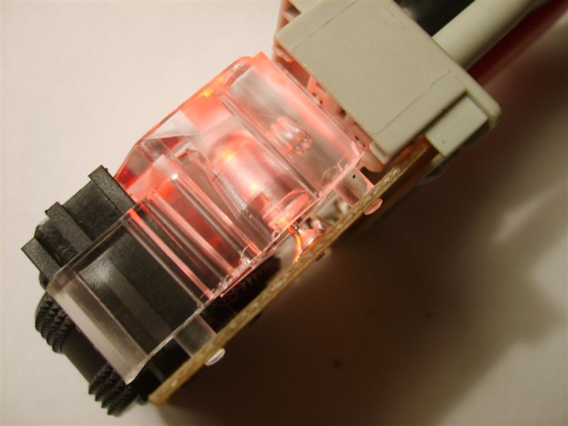
    Was right too, the red plastic light diffuser is clear in the S2's switch. That means it either uses a red bulb or a clear LED that shines red like the big seat heater switch in the last run-through.
    Strangely, saw one on ebay, brand new in the box for less than a new one at a dealers, so thought I'd nab it >> Ebaylinky

    Arrived today.
    Same part number as the one in the TDi, but as said it's subtly different inside and looks to be the same as the one in my S2.
    8A0 941 301 is the number.
    Same process would be needed to change the illumination source as posted further back. You'd just need either a red bulb (number from Maplins given further back) or another 12v clear LED that shines red.

    Here's some pictures of the later headlamp level switch with it's different illumination source for the archives;

    A recap first, the earlier one from my 1993 b4 80 TDi (same part number)


    AND the later updated one (again, same part number)


    Last edited by Jas11n; 2 December 2008, 22:53.

    Leave a comment:


  • Skull
    replied
    Well i have put 2 bulbs in my switch, because the numbers were very bad lit. around 0.5w each, factory coloured in red... the result is very nice.

    Leave a comment:


  • Error404
    replied
    I need to redo one of mine as its marginally brighter than the other dash switches and its irritating my OCD subconsciousness

    Leave a comment:


  • Jas11n
    replied
    Switches coming from germany

    Leave a comment:


  • Acidburn
    replied
    Nice write up jas, did you manage to get the shorter switches off ebay or something? i'm after 1 more of these as i've got 1 of them and two of the longer ones, the longer one's came with a cut up loom which I can't use now so I might just ebay them and keep searching for the smaller switch.

    Leave a comment:


  • Jas11n
    replied
    Again with this switch, there is a tiny part you need to watch out for. A rounded tipped pin sits inside the clear plastic with a spring behind it. If you aren't careful here, that pin will either fire off and you'll never see it again, or it'll have your eye out. It's job is to sit in the position notches on the upper inner rim of the rotary knob


    Now you can finally get to the LED. Refer back to the drawing above to the de-solder points. If replacing with a red bulb, it doesn't matter which way round you solder it, but if you replace with another LED, the shorter leg needs to go to the earth side shown above


    I used a CJ70M 3mm LED for this


    Once done, start to reassemble it. Due to the small components on the board, best be quick with the de-soldering and re-soldering. Heat kills small components


    Testing it is illuminating ok,


    Slotted back in the outer casing


    Done, with the usual out of focus dark shot at the end ops:


    Leave a comment:


  • Jas11n
    replied
    As far as I can tell, there are three versions of the seat heater switches.

    The shorter versions were used earlier in the models life. They are very similar to the headlamp level switches. Two relays were on the aux relay carrier, one for each seat. They were replaced later on with the larger versions and the relays on the aux carrier disappeared. On removal you'll know which you have due to there size.

    I haven't presently got an earlier shorter one, though I should have two of them in a week or so. You can see the difference between the size of them below. One shorter and two versions of the later longer ones.
    Shorter = 5 pin
    Longer = 6 pin
    They do not swap with each other.


    I have two of the later big versions (which are probably the very last of them due to them having LED's from the factory).
    The difference with the two versions of the larger switches is the source of the illumination, differences with the circuit board and a slight difference of the clear plastic light refractor inside.

    If you have this version below, easy job to replace the bulb, with either a new red bulb (Maplins code >>> PG78K), or a red LED (CJ70M), Refer to the control drawing further down the thread for the two solder points and the polarity (Led shorter leg = negative) Use a matchstick or similar superglued to the top of the bulb and withdraw through the hole in the top of the light tube while de-soldering.


    If you have this below, then it's get complicated. There is no hole in the top of the clear light refractor, this version uses a clear 3mm LED that shines red.
    This means you have to do some major de-soldering. You will need a de-solder pump for this and very fine tipped soldering iron.


    Ok, how to open them up.

    Remove the front cover as usual, get your blade and slot it carefully down the side of the rear of the switch. The inner unit is again clipped behind a couple of tangs on the inside of the outer case. The switch withdraws from the front


    You are going to have to remove that massive copper heatsink. Not only is is soldered to the board in three places round it's edge, but also on three places on the centre of the board itself. Use the drawing below. You need to de-solder all the red arrowed points


    And removed


    You have to remove it to be able to remove the clear light refractor. Part of the light refractor is a switch of sorts, that has to be de-soldered to be able to finally get to the OEM LED. The points needed to be de-soldered here are the blue arrowed ones


    Leave a comment:


  • A80Avant
    replied
    sending you a pm again now.links to my photobucket

    Leave a comment:


  • Jas11n
    replied
    Originally posted by A80Avant
    hey jase,did you get the pm with the photos i sent you?
    What photo's are those mate?? Last PM from you was 23-11-08 and no photos attached or anything

    Leave a comment:


  • Error404
    replied
    Originally posted by Jas11n

    Tell you what, I've got a couple of spare door pulls now, I knock up one tomorrow with pictures. It's not as hard as it looks.
    Get out your Blue Peter badge in readiness
    Nice one Jase

    Leave a comment:


  • A80Avant
    replied
    hey jase,did you get the pm with the photos i sent you?

    Leave a comment:


  • Jas11n
    replied
    Originally posted by Error404
    Jase have you got any more info on how you did the door handle strips?
    Missed your question there Alex.
    I didn't take any pictures when doing them, I had my "on a mission" head on and wasn't wholly certain they would turn out the way I saw them in my mind.

    Tell you what, I've got a couple of spare door pulls now, I knock up one tomorrow with pictures. It's not as hard as it looks.
    Get out your Blue Peter badge in readiness

    Leave a comment:


  • YELL MAN
    replied
    Good write up I will be tackling the aux gauges and diff lock this weekend
    Last edited by YELL MAN; 27 November 2008, 17:08. Reason: spelling

    Leave a comment:


  • Error404
    replied
    Jase have you got any more info on how you did the door handle strips?

    Leave a comment:


  • Jas11n
    replied
    Originally posted by Flat on my back
    Is there any way of powering the DL switch on the bench to check the bulb operation before it goes back into the console?

    Works on the bench, not in the car...loom fault...type of thingy.
    On the actual push button switch, yes mate. Apply 12v to the pins on the bottom, using the earth post as pointed out above.

    On the drivetrain image I purposely didn't say anything about that. Reason, apply 12v in the wrong area and you'll do what I did and blow that black three legged transistor thingy when I hooked up the multiplug the wrong way round.
    Check the new bulb before you solder, if it's ok but won't light when back in the car, suspect wiring or faulty circuit board.

    Leave a comment:

Working...