-
-
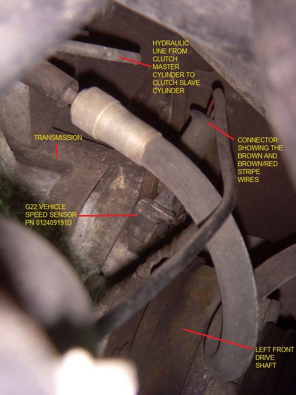
Well it could be the cluster but since you tried another cluster and there was no improvement, you probably need to replace the 012409191D VSS sender. There are a number of options, e.g. Audi dealer, Pete at quattrocorner, etc. and ebay.co.uk:
http://www.ebay.co.uk/sch/i.html?_fr...9191D&_sacat=0
Prices vary.

Leave a comment:
-
So having checked for continuity from vss plug to speedo plug and getting a good connection, plus getting a good 12 v at the vss plug, I'm left with two options, broken vss, or cluster
Leave a comment:
-
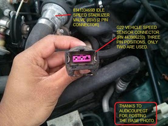
In this case it is relatively easy. Look at the bottom of the diagram for Track 65. Go up and find the G22 Vehicle Speed Sensor. The connector is a three pin. Pin 1 is empty. Pin 2 (in the middle) should have a red (rot) wire with a yellow (gelb) stripe. It is going to Pin 7 in an 8 pin T8e connector. Pin 3 in the G22 connector has a brown (braun) wire that goes to pin 6 in the same 8 pin T8e connector (it then goes to ground at (83) (in the front right wiring loom). Following the red/yellow wire up from the T8e (at pin 7) at some point it enters a T10 (ten pin) connector on pin 8. To confuse matters and do your head in, on the otherside of the T10 connector, this same line turns into a brown wire with a red (rot) stripe which then goes into the instrument cluster via the T26a (26 pin connector) on Pin 20. Once into the printed circuit board of the instrument cluster, it goes to the G21 speedometer.

Leave a comment:
-
Thanks for the diagrams, as hard as it is for me to follow them
i am sure i can work something out with what i have been provided with

any more suggestions as to the cause of my speedo problems are welcome
Thanks guys
Leave a comment:
-
-
Not sure where that first diagram came from but it's different to what I have for the 3B (as dave has now posted)
I'd check you have a good earth to pin 3Leave a comment:
-
-
One easy way to check is to conect one abs sensor instead og the one on the gearbox , you need some speed about 30-40 then it starts to jump ..Leave a comment:
-
sorry dave what i ment to say is i could not find the black t10 connector with the brow/red trace wire under the kickpanel, but a little break from the car and getting my head around that diagram you posted i think i have it sussed now, well so far i have continuity from the t10 plug to the cluster plug so thats ruled out!
just a matter of testing from the t10 back to the speed sensor now, job for tommorow!
ps: you dont happen to know if there is another connector between the black t10 connector and the vss, or is it a straight run wire?
thanks for all your help
Leave a comment:
-
-
connect multimeter to speed sensor at ohm range and turn the wheel. Should change from continuity to open while doing so.Leave a comment:
-
Tested the sensor with a multimeter and some steel to replicate the relucter/exiter ring in box, sensor seems to be working, guess it's just down to me to figur out those diagrams, and locate that plug that speedinggg60 has shown in the pic in daves Quattroworld link. Which I can't find fit the life of me, kinda doing my head in now, thanks for everyone's helpLeave a comment:


Leave a comment: