-
-
The problem with these detailed investigation suggestions is I don't think I need to probe things anymore. It's been figured out. T12b/4 and T12b/3 in the harness and the White and White/Black wires in the RightClick controller. In addition, to do what you ask, the battery needs to be connected and since the battery blocks the central pump control foam box on a C4, the controller would have to be out and exposed before the battery is installed. And then the battery would have to be removed again, etc., etc. after these investigations are concluded.
Sorry not up for it.
Focusing on just getting the Right Click to lock and unlock off the remote.
I'm thinking on removing the two wires from the T12b connector, the brown/grey and brown/green and then using the 4 inch pigtails that I have from a breakers 257D that I have and create a connection/connector that joins the three wires (OE, pigtail and Right Click) for each of the two functions (Lock and Unlock). That way, I won't have to actually destroy/cut/strip any OE harness wiring and things can be put back to OE, as needed, without issues.
Tomorrow.RS2'd 93 UrS4 5 spd sedan
94 UrS4 V8 6 spd manual avantComment
-
The previously used diagram for the 3 plug 257D central locking and lighting control module (where you need one key turn to unlock the one door but two key turns to unlock all the doors) was this:
(note: I've corrected the T6/3 ground labeling issue).

The 257C central locking control module in the V8 avant was only a 2 plug and there was no remote and no alarm. One key turn unlocks/locks all the doors (and hatch) at one time. As result the wiring is simpler:

I just redid the wiring I did the other day to eliminate the Scotch/Vampire taps and now, IT WORKS!! WooHooo.. Unlocks and locks with the Right Click switch blade remote. WOW. (kidding - but it is nice)
Now to hook up the alarm siren/horn (the V8 avant had no such alarm horn).


 RS2'd 93 UrS4 5 spd sedan
94 UrS4 V8 6 spd manual avantComment
-
Mounting the RightClick alarm siren
I was able to mount the RightClick alarm siren in the OE alarm horn location.
I bought this to go with the RightClick RF remote:

By temporarily dismounting a few wire connectors, e.g. the hatch harness connector, I was able to manipulate the aftermarket siren into the OE alarm horn location (in the left rear fender cavity).
Here is the OE Alarm horn in an Avant (sedan is much the same) (I even used the same mounting bolt location). My wiring is more secure than that (ground is hidden and the 12V runs inside the cavity until out of the reach from the hatch area).
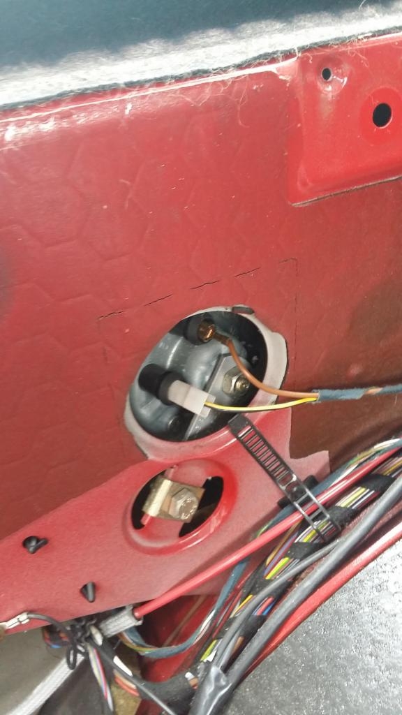
Photo courtesy of hunker7
When I was testing the siren (direct connection to the (+) battery post -just touching a bare wire to the post), the siren didn't seem that loud. When I came into the house for supper, I asked my wife whether she heard the siren. "Yes". Was it loud? "Not really". Was it annoying? "Very". Mission accomplished. RS2'd 93 UrS4 5 spd sedan
94 UrS4 V8 6 spd manual avantComment
-
Missed the door plunger connection *Duh*
Woke up this morning and realized that I don't have the door plungers connected to the alarm. Duh.
Oh well, just one more wire to connect, the T12b/10, brown blue (same as for the 3 plug 257D, etc. controllers, as shown in the diagram under the table).


RS2'd 93 UrS4 5 spd sedan
94 UrS4 V8 6 spd manual avantComment
-
Okay. Wired up and tested the door plunger switches (T12b/10 Brown/blue). I opened the car, got in, put the key in the ignition and turned it to ON. Put down the right rear door window. Got out. Locked the car with the remote. Went to the right rear door. Pulled the door lock pin up and opened the door. Alarm went off. I let it run for about 2 seconds then shut it off with the remote by hitting UNLOCK. Then I locked the car again and then unlocked it. There was some chirping at the siren, like the remote was telling me that there had been an attempted break-in (or something). Not 100% sure.
Also extended the "ARMED" LED wires up to the front of the car. Works. Blinks when Locked/Armed and off when unlocked/disarmed.
I will save the wiring of the parking lights (arm/disarm) and the normal horn (arm/disarm) for another time.
Now to put it all back together.
BTW although I couldn't trace it, I firmly believe that the unknown yellow/blue wire in T12b/8 is the link to the OE window close control (i.e. holding the key in the lock position brings the windows up and closes the sunroof, if open). I tested for continuity between that wire and the 329 window and sunroof module. I got a connection on one of the pins but the wire colour at that pin was NOT yellow/blue so there must be a change in colour at some intermediate connector. I looked in Connector Stn 2 but I wasn't able to find what I was looking for. Oh well, at least I know that 12b/8 is connected to the Window Control Module.
I also tried testing the Rightclick 20 second window close signal to negative with my DDM set to OHMs and connected to that (red) wire and ground - but the test failed (no response). Either my test procedure was wrong OR.....?? 20 seconds would most likely be enough for the closure of the windows/sunroof *IF* they were open when the car was locked remotely. I am not that concerned because the OE key closure feature still works as it did before the RightClick Install.
Last edited by UrS4boy; 11 September 2015, 00:22.RS2'd 93 UrS4 5 spd sedan
94 UrS4 V8 6 spd manual avantComment
-
Your test should have got a reading if it was negative switched but testing for volts as below should get a result
You said your right clic is next to your battery?
Ensure your test leads are plugged into your meter red to red black to black.
To test the 20 second window close signal is 12v+ set your meter to read DC volts Attach Red test lead of your meter to right click close signal.
Attach black lead to chassis ground/battery Negative.
Press close signal to start 20sec output check for 12v+ on meter.
To test the 20 second window close signal is 12v- set your meter to read DC volts Attach Red test lead of your meter to right click close signal.
Attach Black lead to battery+ / 12v+ Positive supply.
Press close signal to start 20sec output check for 12v- on meter.
cheers
SteveComment
-
Just had the AH key cut in the remote.
I had selected AH blanks (two remotes) when I ordered the RightClick KE851HC. Had one of the blanks cut today. Same code that the (same) locksmith figured out before. No problem. Works great.


RS2'd 93 UrS4 5 spd sedan
94 UrS4 V8 6 spd manual avantComment
-
Finally got a straight answer from RightClick:
How should I test that 20 second red wire? ...
================================================== ========
1. Set to DC voltage.
2. Attach the (-) probe to red wire.
3. Attach the (+) Probe to +12v Battery
4. The meter should indicate 12V with the LOCK release button depressed.
5. The meter will then read 0V after 20seconds
RS2'd 93 UrS4 5 spd sedan
94 UrS4 V8 6 spd manual avantComment
-
So I emailed them back, thanking them. 2 minutes later I get this:
" corrections:
***important - For vehicles that have a separate POSITIVE(+) trigger wire for the total closure.
For other vehicles the lock pulse should be extended by wiring the central locking via a relay to provide the Positive trigger..... "

 RS2'd 93 UrS4 5 spd sedan
94 UrS4 V8 6 spd manual avantComment
-
He left out a key piece of information as the email didn't indicate if you should see 12v + or -?
From his description below it looks like the red wire is a chassis ground trigger.
second email goes on to say if you need a positive trigger you have to use the 20sec- pulse to close a relay to provide a 20sec +.
This is why I wanted you to test your close wire T12b 4 by grounding it to the chassis.
This would simulate a longer signal to the close wire to see if the windows close.
You could do another test with the key? How long do you have to hold the key after locking before the windows start to close?Comment
-
To be honest, I am starting to lose the will to live with this RightClick as their "help" is doing my head in. I was happy until he sent the "corrections" email.  As I stated before testing what you want me to test is very difficult because of the location of the controller and the battery, etc.
I think that I will just stick with closing the windows and sunroof by holding the key in the lock position. It starts the process virtually immediately and probably takes 10 to 15 seconds. No biggy.RS2'd 93 UrS4 5 spd sedan
94 UrS4 V8 6 spd manual avantComment
-
My unit has arrived at my house but unfortunately I am 6000miles away off the coast of Brasil
As you say it starts almost immediately let’s look at the original control unit.
Steps to allow car to lock:
1)Car is not running - control unit sees car off through T12b-2
2)doors are all closed-control unit sees doors closed through door switches T12b-10
3)Lock doors with key – control unit sees lock signal through T12b-4
4)Close windows – hold key over in close position
5)Control unit sees all of the above and allows window closure as you continue to hold close the door switch sending prolonged signal to T12b-4
I can’t see anything else happening to close the windows other that the T12b-2 prolonged signal from the lock switch.
I know you are about done with this but if you line tap in to close signal with a length of wire and hold to chassis (same action as holding the key) the doors will close.
Prolonged holding of the wire to chassis ground should close the windows? what you think
Cheers
SteveComment


Comment