You can change the style the forum displays by selecting your preferred style at the bottom left of the site.
We have made an enhancement so that old threads should now link from search results to the correct thread. This is not yet in place for single post links
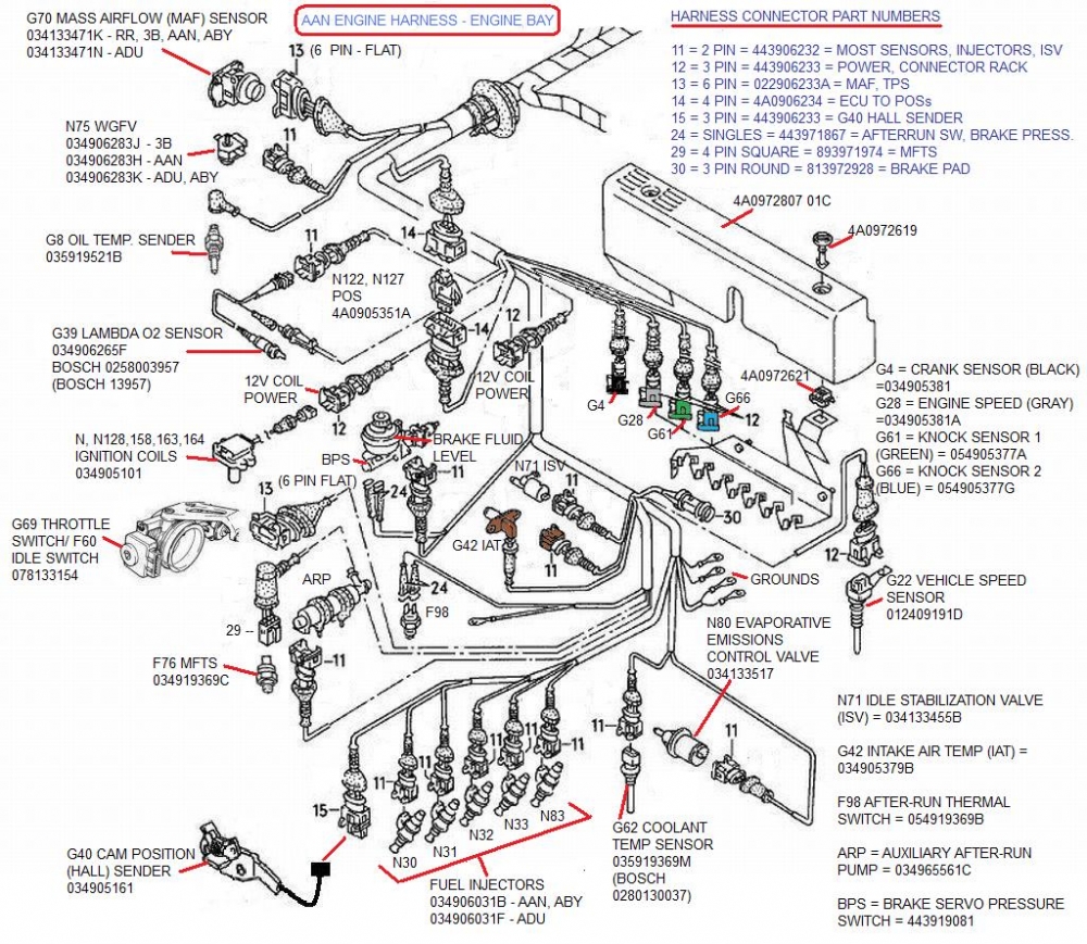
I was hoping that you (someone) would at least spot the N75 location in that 3B harness diagram. I took the similar AAN harness diagram and created this by adding images of the connected devices and the part no.s of the the devices (along with the connector PNs). I was thinking of something similar for the 3B and/or ABY.
Thanks for the help guys! This has been a very tough part of the project for me so getting some good help is very refreshing and motivating
So, I took a pic of what I think should be position 1 for the blue/red wire (on left) and the Green/Gold to be in position 2(on right). Would this be correct?
There are two wires going to the N75 WGFV, one power, one control. For the AAN, these two wires are:
1. a red switched power wire that comes from the S75 circuit breaker (the black one) above the ECU and goes to Position 1/2 on the WGFV
2. a yellow wire with a red stripe that comes from the ECU (or goes to the ECU, depending on your point of view) at Pin T55/33 in Position 2/2 on the connector.
For the ABY, according to Paul N.'s S2net website, the WGFV wire colours are
blue/red for the power wire in Position 1 and green/gold for the wire connected to the ECU at T55/33.
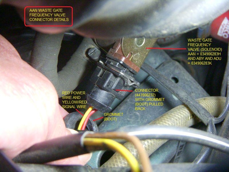
Just checked my AAN. The red power wire is on the right side and the yellow/red wire is on the left, this is with the bail (wire) up and the groove in the connector up (to match the tang on the WGFV).
So for the ABY, I think this means that the blue/red wire is on the right and the green/gold wire is on the left, connector groove/tang up.
This is the opposite of your photo.
RS2'd 93 UrS4 5 spd sedan
94 UrS4 V8 6 spd manual avant
Thanks for the info! I'll go with how you mentioned. Still looking for a spare male connector to use so I don't have to cut up my good harness.
A little background on my project: I started out 2 years ago with a '91 90 Quattro 20v and have been trying to make it better bit by bit. First stuff was cosmetic and now we are into the performance chapter I've been at the 3b swap for over two months now and am nearing the moment to turn the key and cross my fingers.
Next question: What color wire goes to the oil temp sender on the front of the motor?
Again thank you for the info - this is helping a lot!
Just checked my AAN. The red power wire is on the right side and the yellow/red wire is on the left, this is with the bail (wire) up and the groove in the connector up (to match the tang on the WGFV).
Took a photo (or two) and annotated one for now in case my words didn't make sense:
RS2'd 93 UrS4 5 spd sedan
94 UrS4 V8 6 spd manual avant
Next question: What color wire goes to the oil temp sender on the front of the motor?
The G8 oil temperature sender is a single pin resistance-based sensor (see photo below). There is only one wire and it is most likely black and is probably shrouded in a rubber cap (as shown in the AAN engine bay diagram I posted above).
Thanks for the info! The wire coming off the oil temp sender is Black/Brown.
I spliced a couple of the interior connectors, one was the T10/T5 Black connecter which I believe houses most of the oil/temp signals. The other is the black plug that hooks into the fuse panel.
T10/T5: I connected everything that matched colors and was left with what's shown. Where should I connect the rest?
Fuse Panel connector: The existing 3b one was missing the Red wire(which was snipped I believe). I used the 7a plug and matched pins on this one and only one wire was different, shown in pic. There is also one wire that doesn't have a home(does it need one?)
A few loose wires in the bay:
Green plug inside I don't know where it should go:
Again thank you everyone for all the help! I'm so close to being able to attempt first run, just a few more bits after this wiring is sorted.
That helps identify what's what with the 7a thanks! The 200 one is different than the S2 3b unfortunately. It seems there's really good documentation for the ABY setup but for some reason the 3b is lacking a little. Were there a lot more ABYs manufactured?
Unfortunately it still isn't 100%. I need to do a tech session with Dave and try to figure out what signal is angry. The mfts is still unhooked.
So what it does is every time I go for a drive, I can get full boost once. Sometimes it's for a second but have had it work for 5 seconds before. I have noticed that the boost build isn't always smooth, meaning it will get to about 7 psi and then bounce to 12 then right back to limp mode. I can shut off the car while rolling, start it and have full boost for another second or two. I could repeat that all day long.
I've heard that the mfts is needed for the ecu to be happy but I've also heard that it's not needed. I've been driving it this way for the past 4 months or so and other than this limp mode issue it runs great.
Hopefully that gives you enough info but if not let me know and I'll take pics/give more details so we can get it sorted out
We process personal data about users of our site, through the use of cookies and other technologies, to deliver our services, personalize advertising, and to analyze site activity. We may share certain information about our users with our advertising and analytics partners. For additional details, refer to our Privacy Policy.
By clicking "I AGREE" below, you agree to our Privacy Policy and our personal data processing and cookie practices as described therein. You also acknowledge that this forum may be hosted outside your country and you consent to the collection, storage, and processing of your data in the country where this forum is hosted.



 I've been at the 3b swap for over two months now and am nearing the moment to turn the key and cross my fingers.


Comment