
Well unknown chips and a checksum error would tend to suggest an issue. As you have suggested a subsitution would prove that!
Sometimes if you are lucky a diagnostic check with VCDS would bring up a Vendor. Withot knowing their origin, its difficult to comment.
Is the engine stock otherwise?
-
-
Motronic ECU opening hints
This is for the OP, not you Robin:
ECU opening pdf: http://12v.org/urs/Bob%20Myers%20ECU...structions.pdf
ECU opening video: https://www.youtube.com/watch?v=CBX22emnv0k&fmt=22

Leave a comment:
-
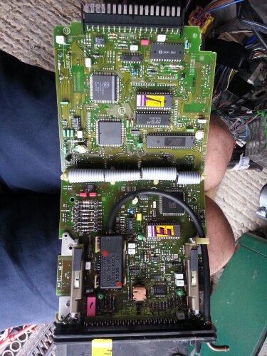
It is chipped I know that for certain, have already opened it once The problem is knowing it's good....
Leave a comment:
-
A low tech way of assessing whether the ecu has been chipped is to inspect the tabs that secure the cover on the rear. There is usually evidence of pry marks as the tabs need to be bent up to remove it!
However if you really want to know you will have to open it. Not that difficult but there is a knack to it!Leave a comment:
-
Nope fuelling is fine.... well saying that how would I know but I turned off the engine and restarted the car it started fine but still showed the 1111 code !
I'm going to check the ground connections as per SJM:
65535 1111 Engine Control Module Malfunctioning Poor ground connection to J220 at pins 10, 14, 18 or 24 / No voltage at pin 37 of J220 while cranking
Check J220 wiring, B+ and ground connectionsLeave a comment:
-
Your quote obviously is for an Hitachi ECU from a 10V turbo. Here is a 1111 code discussion relating to the 20VT Motronic ECU (similar to your quote):
•1111 (Blink Fault Code), 65535 VAG1551/2 Fault Code Number
Engine Control Unit (ECU) Defective memory circuits,
Incorrect Checksum for internal memory (EPROMs)
(this can occur on some modified ECU's) Check ECU ground connections, Check EPROM programming
Symptom: Check engine light may come on
Nothing about shutting the engine off. Are you sure 1111 was the only code and/or you don't have fuelling issue?Leave a comment:
-
ECU Fault 1111
Ohh an update....
I just popped out, as I do now and again and check that the engine starts runs etc. It started, it ran, so I left it to warm up for a few minutes, then it stopped.... I have the Diagnostic LED in a blackbox attached to the loom so I held the button for 4 seconds and asked the ECU for a diagnostics code, the code I received was 1111.
Now I would have thought that ECU code 1111 couldn't be intermittent, it works or it doesn't because electronic components don't have bad days, its 1 or 0, on or off.Code 1111 - ECU
The ECU itself has failed one of its own diagnostic tests. The most common cause is a bad PROM checksum resulting from incompetent "chipping" - some companies apparently do not know how to recalculate the checksum after modifiying the boost tables. Remove the cover from the ECU, unscrew the upper board, and check that the original Hitachi PROM (it has a silvered sticker saying "MAC12") is still in place. The stock chip is soldered directly to the board - a modified chip will usually be in a socket. If the chip has been changed, a new chip with a correct checksum should be sourced.
Otherwise, check the ECU in a known good car.
Anyone have any ideas how I can check the ECU I have, or a stock Chip I can drop in to replace the chipped one I have just in case this IS the actual issue?Leave a comment:
-
I had a look at the ECU plug and the ECU location and have made a few changes... hopefully this will make my problems go away

Full article here:RussellWeb.EULeave a comment:
-
Well that is good news.
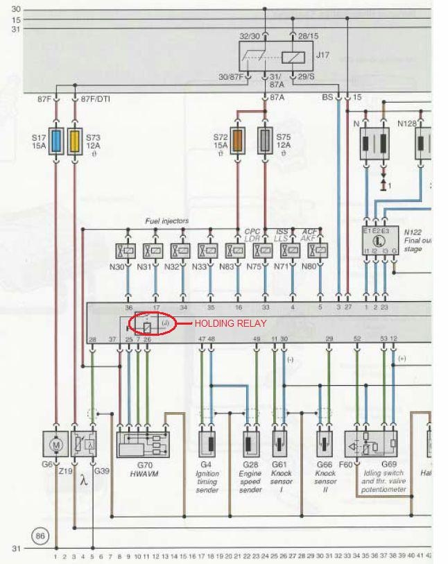
Wiring is wiring. You have to stick with the original design intent or something will go kafluey elsewhere. This AAN J17 Fuel Pump relay diagram shows what you are talking about (where S72 = ABY S28 and S75 = ABY S24 and S17 = ABY S13)
 Last edited by UrS4boy; 5 May 2014, 21:08.
Leave a comment:
-
Hi all,
So I have just been out and had a play and...... I made a wiring mistake an an incorrect assumption!
If you look at the FP relay pins 87 and 87a are switched via the relay and supplied by constant 12v from the battery rail in the fuse box. I assumed you could mix and match these outputs, you can't!
I had the fuel pump fuse and s28 connected to the same output pin on the relay, 87. If you follow the diagram you'll see s28 passes through the air mass sensor and cross connects via a hold over relay in the ecu, this was also powering the fuel pump... Oops!!!
I've now isolated the outputs from the FP relay as originally designed, although the lambda heater is switched via the ignition as per the original Audi 100, not as above, although I may change this later.
The big ecu plug still has an issue and I think this may simply be because of the sealing ring being missing, or the casting screw not being the original screw and therefore not the right size. It's working but it's temperamental so I'll need to run through that.
Due to an accident in my day to day car I can't risk going for a test drive at the minute as I can't recover myself! As soon as my daily drive is repaired I'll be testing again.
Thanks to your collective input, it is very much appreciated.
Sent from my iPad using TapatalkLeave a comment:
-
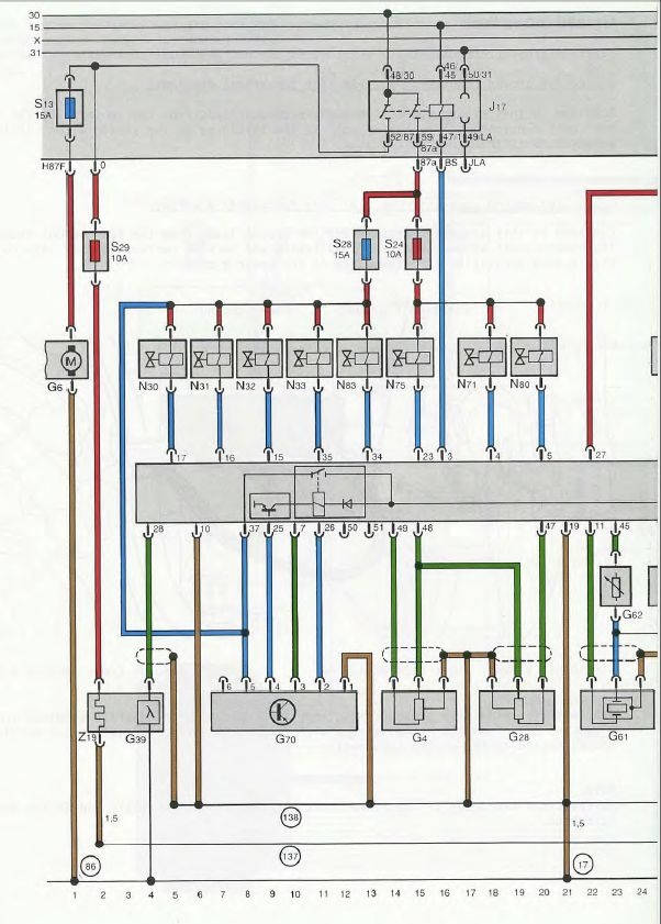
Here is some info that I have put together about the J17 Fuel Pump Relay

Bottomline, for the AAN, ABY and ADU, unless the ECU gets a signal from the G28 that can be interpreted as the cranking speed is over 13 RPM, the ECU will *NOT* energize the J17 FP relay. This means no power to the G6 fuel pump, the injectors, the G70 MAF (at least not full power) or the N71, N75 and N80.
Leave a comment:
-
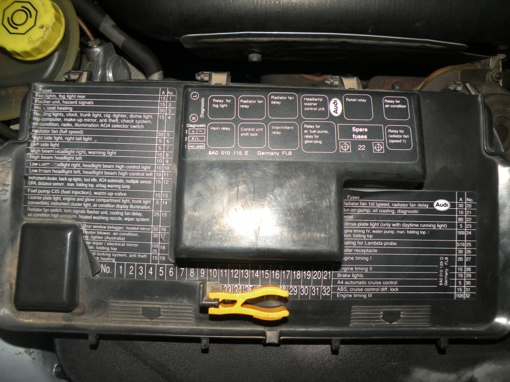
I'm away from home until Monday so I can't check on the car, but yes the blue wire is from the ecu. The red wires are live feed, the black ignition key feed (and the small blue ones on the right also). Comparing the fuse numbers with the picture you posted things are correct. I need to check the ecu pin is correct, but I'm pretty sure it is.
Do you know how the ecu decides when the fuel is primed?
For the FP relay it's only got one in/out pair right, the other pairs are for the fuse override in the upper housing?
Sent from my iPad using TapatalkLeave a comment:
-
-
uploadfromtaptalk1398871060992.jpg
Although simplified compared to the original. ..it does the job
Sent from my GT-I9300 using TapatalkLeave a comment:

Leave a comment: