You can change the style the forum displays by selecting your preferred style at the bottom left of the site.
We have made an enhancement so that old threads should now link from search results to the correct thread. This is not yet in place for single post links
Hi
Can someone point me in the location of the power feed from the relay to the fuel pump on my 3b?
I currently have the dash out.
The wire is green with a yellow stripe at the pump.
I'm trying to find out why I don't have power to the pump.
J17 Fuel Pump Relay Information and why it is so important
Originally posted by Dobby84
I'm trying to find out why I don't have power to the pump.
Cheers
Because the ECU controls the energizing of the J17 Fuel Pump relay and it only energizes the relay *IF* certain conditions are met, not just the key turned to RUN.
Read this:
J17 Fuel Pump Relay Information and why it is so important:
The Audi Enthusiast website. Forums for all Audis including A4, S4, A5, S5, A6, S6, allroad, A8, S8, TT, R8, Q5, Q7, 4000, 100, 200, v6, v8, vintage, local forums
RS2'd 93 UrS4 5 spd sedan
94 UrS4 V8 6 spd manual avant
I know there are various things that have to work but at when I put a 12v supply directly from the battery it starts up fine. The relay is working as it should, I have added an LED to indicate that everything working as it should. This is why I thought I would run a new wire from the relay to the pump to see if this solves the problem.
Also that diagram doesn't mean much to me, never understood them. Lol
Also that diagram doesn't mean much to me, never understood them. Lol
Then you should take a bit of time and learn. It will be worth it later.
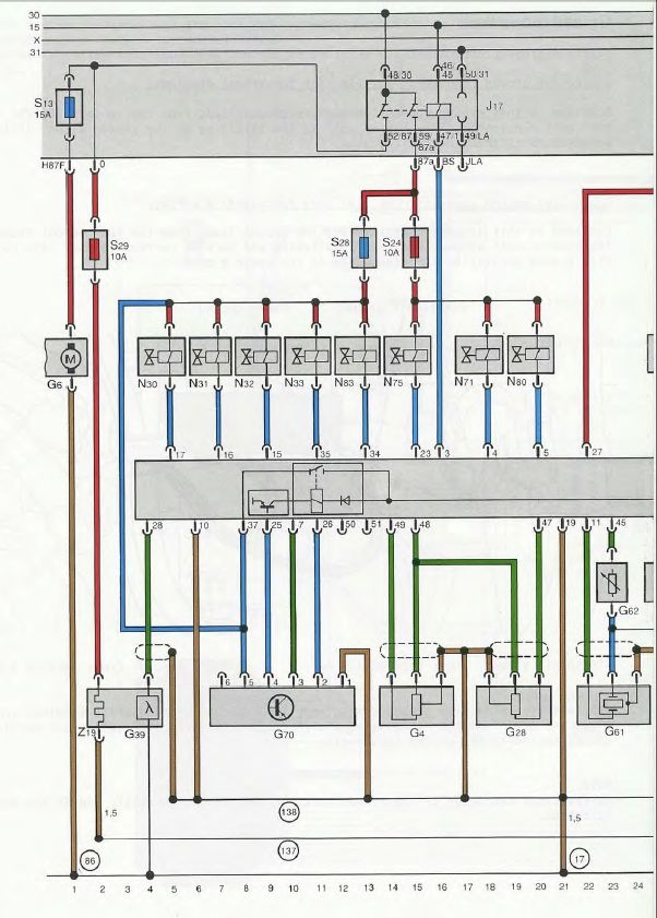
There should be a green wire with a yellow stripe coming out of the S13 Fuse (did you check the fuse? Sometimes they look good but in fact are blown). You could check for continuity between the right (left?) side of the S13 Fuse holder and the connection at the top of the fuel pump. I'm betting that it is just fine.
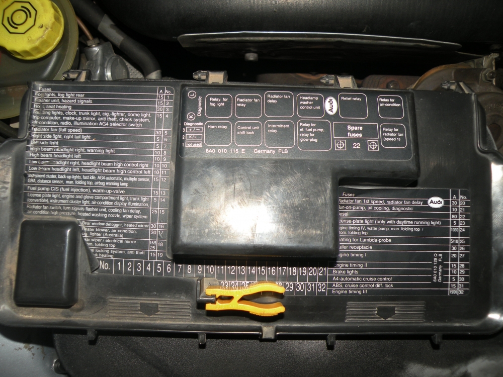
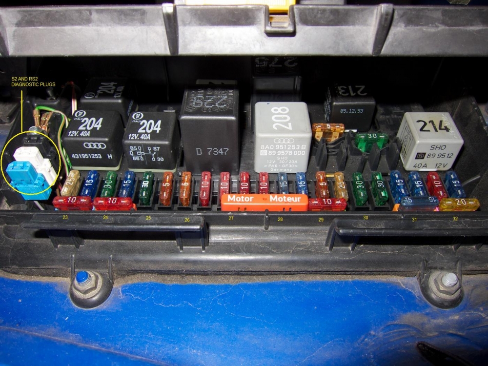
S13 is the blue 15 Amp fuse just above and to the slight right of the "r" in "Moteur":
RS2'd 93 UrS4 5 spd sedan
94 UrS4 V8 6 spd manual avant
The 'T' terminal is one side of the resistor nearest the corner... solder the -ve (cathode) side of a 12V LED to that pin
Attach the +ve side the 12V LED to the 87 or 87a terminal... this is NOT the other side of the resistor
According to his thread the LED should light up when cranking the car and indicates that the relay is working correctly. My car has 215 relay rather than a 208, I assume this is correct for a 3B as I have never changed it.
I have checked all the fuses in the box and they all seem visually fine.
When I removed the Cobra alarm I traced all wires from the alarm's loom and cut it from the car's loom where it they had been spliced in. I reconnected the original wires using crimps. There was not wires connecting to the green wire with yellow stripe which I was surprised about. Maybe I have missed something or there is a separate bridge that was not connected directly to the alarm loom.
I will check the G28 speed sensor and G4 crank sensor next time I get my hands dirty to make sure they are connected.
That's one thing I haven't checked yet. What is the easiest way to do this?
If you have a nice sharp point on the multimeter lead you should be able to get a measurement through the little hole in the top of the actual fuse. Red lead there, black lead to chassis.
Otherwise take the fuse out and probe down into the fuse holder, should be power one side, then buzz the fuse to make sure it's ok.
If you have a nice sharp point on the multimeter lead you should be able to get a measurement through the little hole in the top of the actual fuse. Red lead there, black lead to chassis.
The relay has 2 sets of contacts, it's possible your led is fed from the set that powers the Lambda and the other set is not working.
I followed these instructions:
I don't have a formal guide as such, but its pretty simple...
The relay has these terminals numbered underneath:
30 - unswitched 12V
T - pulled to 0V by the ECU when it is happy the engine is spinning... connects to one side of solenoid
86 - other side of solenoid, connected to switched 12V
87 - to fuel pump and lambda heater
87a - to injectors, maf, isv, evap & wgfv
When you pop the hood of the relay you can see an internal ballast resistor - you can verify connectivity around the internals with meter. I might have a photo that I can annotate.
The 'T' terminal is one side of the resistor nearest the corner... solder the -ve (cathode) side of a 12V LED to that pin
Attach the +ve side the 12V LED to the 87 or 87a terminal... this is NOT the other side of the resistor
Yes I know, so you either soldered to 87 or 87a, the other set of contacts is not monitored by the LED.
It's a long shot but possible the one set of contacts works and the other doesn't..
Anyway if you you have power at S13 and you can run a wire from S13 to the pump and it runs then the MUST be a break in the green/yellow wire
Yes I know, so you either soldered to 87 or 87a, the other set of contacts is not monitored by the LED.
It's a long shot but possible the one set of contacts works and the other doesn't..
Anyway if you you have power at S13 and you can run a wire from S13 to the pump and it runs then the MUST be a break in the green/yellow wire
I did try running a wire from the relay to the pump with no success but then I may not have had a good connection or the right connection to be honest. It started raining so gave up. Ill check the fuse and if its working then I will try running the wire from that instead. Does the green/yellow wire feed anything else or just the pump?
I tried finding this wire under the dash and fuse box but couldn't see it but will have another look.
We process personal data about users of our site, through the use of cookies and other technologies, to deliver our services, personalize advertising, and to analyze site activity. We may share certain information about our users with our advertising and analytics partners. For additional details, refer to our Privacy Policy.
By clicking "I AGREE" below, you agree to our Privacy Policy and our personal data processing and cookie practices as described therein. You also acknowledge that this forum may be hosted outside your country and you consent to the collection, storage, and processing of your data in the country where this forum is hosted.






Comment