
In fact just pull the plugs to the 3 devices and see if you have 12v going to them with the ignition on.
-
-
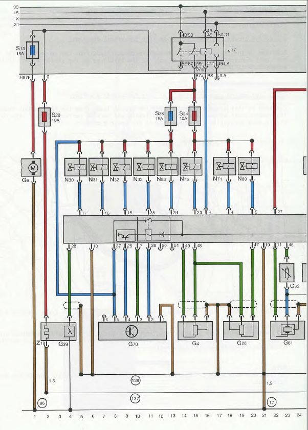
S24 and the N75, N80 and N71 that it feeds is energized by the J17 Fuel Pump relay. Not sure about 3Bs or ABYs but I know the AAN's J17 is not energized by the ECU (via pin T55/3) until the ECU gets a signal from the G28 engine speed sensor that the RPM during start is >13 RPM. Weak battery and <13 RPM = no start because the J17 isn't energized. So testing with just the ignition on would not work on an AAN, not sure about 3B/ABYs.
 RS2'd 93 UrS4 5 spd sedan
94 UrS4 V8 6 spd manual avantComment
-
Might need to crank it over to see the voltage then
Or why not try the output tests for the devices on VCDS??Comment
-
Dave you might be right as I have just tested the three plugs and no power at all so will try cranking the engine tomorrow I imagine it will be the same for ABY as for the AAN.Comment
-
Might? I am very confident that I am right (i.e. you can't test the N71, N75 and N80 for power on a stopped engine - and maybe not a cranking engine, might as well just start it).
  (NOTE: The N71, N75 and N80 are all controlled by the ECU by the ECU grounding them through the ECU, they have power once the engine is started)
More reading about the importance of the J17 Fuel Pump relay (and how it controls power to the injectors and N71, N75 and N80) can be found here:
RS2'd 93 UrS4 5 spd sedan
94 UrS4 V8 6 spd manual avantComment
-
I would have thought that if you have VCDS that you can measure power at the plugs during the output test with just the ignition on. Other than that the manual suggests measuring whilst cranking the engine.
I think those components as have been suggested previously are all supplied power commonly through one set of contacts in the fuel pump relay, so its possible thats kaput. You can remove the top of the relay to check or susbsitute a known good one.
If you have VCDS use the output test. No clicking or clanging on all would point to the power. You will need to work back up to the relay to see where the issue is.
HTH!Comment
-
Just tested the plugs with engine running no power present in any of them. So sounds like the fuel pump relay is faulty?Comment
-
Well, if the engine is running, then at least some of the fuel pump relay is working. Even the part that might not be working, i.e. the part that feeds the S24 fuse must be working because the same 59/87a relay leg also feeds the S28 injector fuse. How are you testing for voltage at the N71, N75 and N80 connectors?
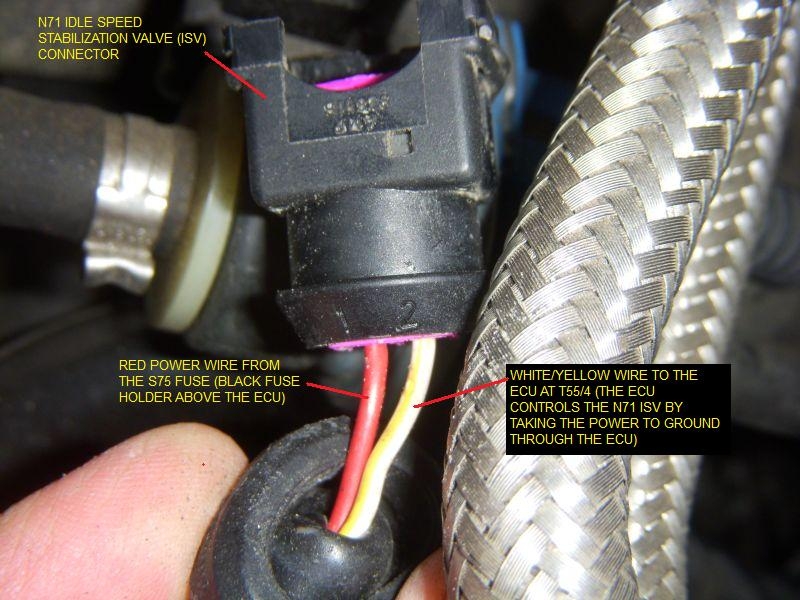
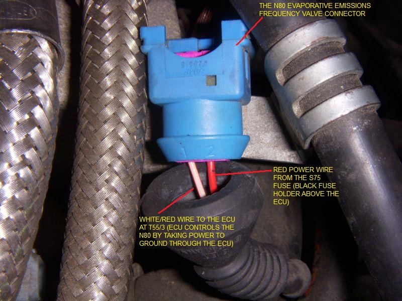
For example, for the N71 and N80, you need the DDM set to 0-20 VDC with the end of the DDM (+) probe in the red-wire pin with the (-) probe grounded to engine somewhere close.
N71 wiring (S75 is the AAN equivalent to the S24 in your car)
N80 wiring
RS2'd 93 UrS4 5 spd sedan
94 UrS4 V8 6 spd manual avantComment
-
Go back and test to see if there is power at fuse 24 with engine running. If you have power at the fuse and the fuse is ok then there must be a break in the wiring to the components. If there is no power you will need to check between the fp relay and the fuse for continuity.Comment
-
0.01 what?Comment
-
VoltsComment
-
No!
We are looking at getting 12V at one of the connector pins(of the 2).
Are you confident with electrics?
Not being rude but it makes a difference to how we explain things. Although Dave has had a good go!Comment




 (which is why I reposted the wiring schematic)
Comment