You can change the style the forum displays by selecting your preferred style at the bottom left of the site.
We have made an enhancement so that old threads should now link from search results to the correct thread. This is not yet in place for single post links
The two way supply is a bit confusing. Wonder when the holding relay drops out of the loop. During cranking/running?
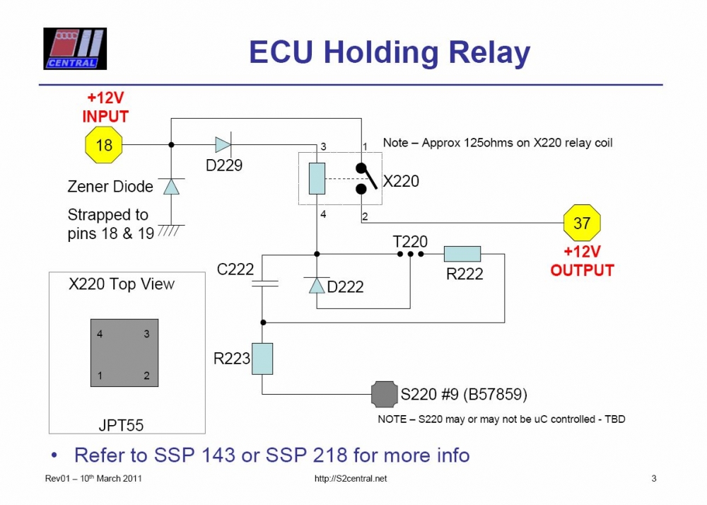
I agree on all counts, especially the confusing bit. It took me a long while to accept that power to those devices can come from two directions without issues. I eventually figured it out, no doubt with some input from Paul Nugent, reading what he had said about it. The secret is probably in the Holding Relay diagram that Paul N. did. Suffice it to say, the Holding Relay is involved before the engine is started and after the engine is stopped but very likely not while the engine is actually running.
RS2'd 93 UrS4 5 spd sedan
94 UrS4 V8 6 spd manual avant
I was trying to determine whether its acting as a check engine light in effect.
So would illuminate with ign on and go out when engine started and if illuminated with engine running, that would indicate a fault.
I was interested on what Paul N said about the holding relay and its connection to the K line from the ecu.
Not sure how the check engine light is connected to the ecu.
Have you tried disconnecting your black box temporarily.
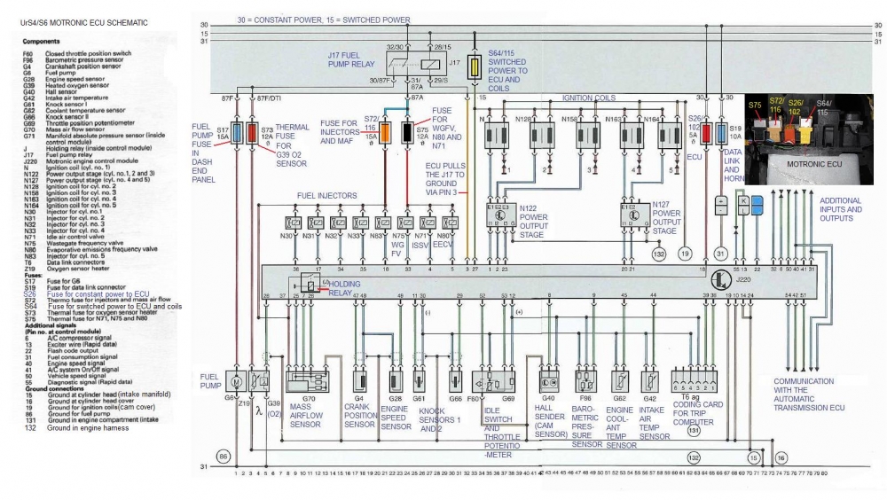
I can see that Pin22 is the connection for the lamp. I am assuming that the ecu grounds the lamp to light it as the other end would be powered up. So that leaves us with why the led flashes. Is it loosing power or being switched at the ecu?
The logic (if any) of temporarily removing the black box is in case it is somehow influencing the ecu. My understanding is that if you jumper the L line before turning the ignition on you activate the output tests, one of which is the ISV which you state can be heard in your video. I was wondering if somehow that is occuring inadvertantly.
I will give that a go. My guess is the ecu powers or rather switches the ground for the LED when the ignition key is turned on, which by reference would imply the switched 12v supply or one of the grounds is an issue. When I looked last night I unplugged the ecu and checked the connections in the plug to ground. Pin 19 wasn't instantly good, so as with all troubleshooting I'll start there and move on to the chips, black box etc.
I wish I could force the error as then I have a benchmark by which I can measure all situations, components and combinations thereof.
Not sure how the check engine light is connected to the ecu.
Have you tried disconnecting your black box temporarily.
From S2Central.net. I *HATE* frames. Can't create links.
"Instrument Cluster - MIL Circuit
Introduction | Removal Procedure | Related Information | Autocheck Info | MIL Circuit
Tools Required :
Cross-headed screwdriver
Long thin 'terminal' screwdriver
Miniature screwdriver or probe
Soldering Iron, Wire strippers, cutters & Pliers
8mm socket & driver
An optional multimeter can be handy !
Time Required :
About 1-2 hours, depending on electrical skills
Parts Required :
2W inst bulb (green) 893 919 040A
1m length of cable (0.5mm2)
Splice or Spade connectors - your choice
Small tie-wraps and/or insulating tape
WARNING !
It is not absolutely necessary to disconnect the battery before doing this job as all the relevant connectors have female plugs, but it is better to be safe than sorry with all electrical tasks and the negative lead at the battery should be disconnected if you are in any doubt about proceeding further.
What is the MIL circuit ?
It is a little known fact that Audi 80 & Coupes exported to the USA had to comply with Californian legislation which dictated that the driver had to be informed of certain (emission related) engine fault conditions by means of a warning lamp. This is known as the Malfunction Indicator Lamp - or MIL for short.
The MIL circuit is not fully wired up on Audi 80s & Coupes that were not destined for California, but I have discovered how to activate this function on the S2 after many hours of 'reverse engineering' the instrument cluster and probing round the wiring loom.
Why should I be interested in a MIL circuit ?
The MIL circuit is connected to the blue coloured OBD plug that is fitted to the car which is ultimately controlled by the ECU. This same blue (MIL) plug can be used to retrieve fault / blink codes from the ECU.
All of this means that, by adding a MIL circuit onto the S2 cluster, there would be no need for messing about with LEDs and test lamps to pull fault codes . But more importantly, the MIL circuit will inform the S2 driver of many active fault conditions that the ECU can detect whilst the engine is running. It does this by illuminating the MIL until the fault clears. Any faults are stored in the ECU and can then be blinked out on the MIL as soon as it is convenient to do so.
The cost of adding the MIL circuit is very low indeed - needing only a single instrument bulb, a short section of narrow guage cable and a connector or two.
NOTE - The MIL circuitry does not flash out the blink codes until the blink code sequence is activated as normal. This prevents driver distraction.
How do I wire up the MIL circuit in my S2 ?
The following gives a fairly detailed description, in three parts, as to how the MIL circuit can be activated on the S2. I have proved it out on my 94 ABY but it has also been proven out on a 3B. It is very simple electrics requiring a single wire be added to the loom and a new bulb be added to the instrument cluster in an unused location. Some soldering skills are needed along with basic electrical tools.
Some links below are to related pages on this site, others link to decent sized JPG photos. There are also some embedded images in this page where necessary.
PART 1 - Preparing the Loom
Firstly, remove the instrument cluster as described here , and set it to one side in a safe place to prevent damage until Part 2 below.
Locate the yellow coloured 26-pin connector (T26) behind the instrument cluster and snip off the tie-wrap which secures the wiring to the connector shell. Be extra careful to only snip the tie wrap !
Using a miniature screwdriver (or a fine tipped probe), tease apart the hood from this yellow connector and slide it off to expose the electrical wiring and connection pins as shown in this photo .
Locate pin 24 (twenty four) on the yellow connector. The connector moulding is numbered to assist with this task - it is two from the end as shown in this photo . Pin 24 is an unused connection point, so there should be no wire attached to this pin - until these tasks are complete. If your car is an MY95 vehicle, fitted with the factory immobiliser, then this connection point must NOT be used. Click here for more details and an alternate lamp location.
Again using the miniature screwdriver (or probe), GENTLY disengage the locking tab for pin 24 and remove it from the yellow connector, as shown here .
A special crimping tool is specified for these pins, which none of us will likely have access to, so I recommend that a soldering iron is used to connect a 1m length of multicore (0.5mm 2 diameter) cable onto this pin. If you choose cable which is too thick then this will be difficult and the pin may not fit back into the connector.
Carefully return the locking tab of the connector pin (with new wire attached) to its original position and slide it back into position 24 (twenty four) of the yellow cluster connector. It will lock itself into place.
Reassemble the yellow connector hood, taking care not to snag any cables and attach a new tie wrap onto the connector hood when finished. With this new length of wire dangling from the yellow cluster connector the fiddliest task is complete.
PART 2 - Preparing the Cluster
Now the attention turns to the instrument cluster... With the cluster lying face down on a soft surface, remove the sticky cover for the unused 'CAT' warning lamp as shown in this photo and fit the green 2W lamp in this location. At this point it is worth noting that the early cars have an unused yellow warning symbol that resembles a steering wheel in deference to the 'CAT' legend on later cars. Dunno why - but I'm 100% sure that this is the correct lamp location for the MIL bulb on Californian cars. This link lists the different warning lamp legends applicable to the S2. Please note that if you have an MY95 S2 (S chassis) with the factory fitted immobiliser - you will have to work with the unised lamp location above the 'CAT' lamp. More details here.
Reconnect all of the electrical plugs back into the instrument cluster as normal.
At this point, you may wish to test the newly installed cable and CAT lamp. Do this by turning on the ignition and then touching the other end of the new wire to the chassis (0V). The red CAT lamp will only be lit whilst this circuit to 0V/earth is closed.
Temporarily loop or tuck the new section of wire in behind the instrument cluster which can then be refitted as normal.
PART 3 - Completing the MIL Circuit
Now working in the driver side footwell, use an 8mm socket to remove the four bolts which secure the parcel shelf to the dashboard. Three bolts are on the top edge, and the fourth is down near the bonnet release.
Slide the parcel tray carefully out of the plastic clip at the pedals. If your car has diagnostic plugs in the drivers parcel shelf (early 3B only) then you may wish to unclip them, so that the tray can be moved out of the way for the next tasks. Try not to panic when you see the mad rampant mess of spaghetti cabling which is lurking under the dash. Fortunately, the access you need is very easy.
Locate the new loop of cable which connects to the yellow cluster plug from Part 2. Unloop it, then tie-wrap and/or tape it along the existing loom from the cluster such that it makes a sensible route to the black 5-pin connector (known as T5) shown in this photo . This is where it will connect to the 'blink output' driver from the ECU. Leave enough slack cable to work with for the new connection point.
Looking at the T5 connector, you will see a gray/brown (gr/br) coloured wire on the pedal side of the connector which is unterminated. On the ABY engine this corresponds to pin 4 (four) on the T5 plug, but it is pin 3 (three) on the 3B engine (thanks to Steve Henson for confirming that). This is the wire needed to drive the MIL function. As a double-check, you can perform a continuity test with a multimeter from this wire to the BLUE diagnostic plug on your car. The reading should be a short circuit (0 Ω) confirming that you have located the correct wire !
Trim and connect the new wire from the cluster to this gray/brown wire on T5. An ideal connection would be with a crimped pin that inserts into the empty receptacle of T5 but such connector pins and crimp tools are very hard to find. Other ways to make the connection are with insulated male & female spade terminals or with a 'scotchlok' style connector. The latter has the advantage of not needing to cut into the gray/brown wire and fiddle about with wire strippers and crimpers etc. Either way, make a secure connection and ensure all the wiring is neatly and safely taped or tied into the factory loom.
Now turn on the ignition and look with awe and amazement at the newly illuminated 'CAT' lamp which serves as a wonderful Malfunction Indicator Lamp (MIL).
...Been prepping for tomorrow and I see only pin 19 connects to earth point 138, so a bad connection there IS possible.
There are several grounds, 19 is an important one but there are others, e.g. 10, 14. 24 and 19 (as shown on this AAN diagram). (Note: They all end up grounding to either the cam cover or the intake manifold).
RS2'd 93 UrS4 5 spd sedan
94 UrS4 V8 6 spd manual avant
Yep they are all important, but what I was trying to show in my diagram is pin 19 goes to the earth group 38, which is the twist of wires into a plastic cap in the loom that is then connected to the inlet manifold.
Gut feeling again, but it is easy for that one wire from pin 19 to the earthing group to be dodgy, frayed, partly broken etc. The other ground connections go directly to earthing points.
That diagram is useful so I will add it to my reference list!
19 seems okay...dropped the chips in, drove to the local petrol station, taking it easy, driving back gave a bit more welly, blew a turbo hose off....I'll give a longer account later was scarily fast!
Sounds encouraging!
Guess its a bit late to lecture about using the stock wategate spring but obviously std SW is designed to operate with the stock spring as is most reasonable upgrades. Having an uprated spring sort of overrides the safety features.
Be worth double checking what you have before going mad. You will have to remove the wastegate cap to a look and post a pic so that we can try and id it hopefully!
I started off this afternoon by checking the earth, then I moved on to a few other tasks, the side repeaters need replacing and the offside rear mudguard support needed a stabiliser...which half way through welding I ran out of wire! Enough welded for now but next week I'll get some more.
Having finished those tasks, I popped open the ecu, swapped the chips over and put the ecu back in. The car started and idled okay, so while I put my tools away etc I let it idling....and it cut out. I thought ok, I'll give it a second chance and started the engine again, it idled okay and I decided to don the helmet and go for a jolly, fully aware of the fact I had no recovery on standby and the local Asda petrol station is at the end of a hill, so it would be uphill going home!
Slowly out of the estate, all good. First set of traffic lights pulled away accelerated slowly,what a sound, in to the forecourt stepped out threw £20 in and started the trip home. Sat at a red light again and some guy in a focus nearly totalled it staring at the car and not looking where he was going, always funny that!
Driving up the hill towards home, about 500 meters before I turn into the estate I thought let's wind this up a bit,and away she went then pop! Hazards on and coasted over to the side of the road. Bit of a busy road so was a bit risky but not a lot I could do.
I had an idea what it was, took the engine cover off but couldn't get to the pipes in the offside pod as it was in the road. All the pipes reachable under the engine cover where fine and I could get the engine to start and drive 10 meters before it cut out... So with a few (5-6) times of repeating this I could get into a side road and crawl under the offside. The intercooler out pipe had popped off, I could just pull the clip off the end and slide it back onto the intercooler and drive slowly home.
The clamp is an easy fix, but I do need a size down from what I have now. I haven't adjusted the clamp in the photo, and as you can see it was on its tightest setting.
As soon as I get that fixed I'll be out for another test drive, and then to prove the fault I'll have to put the original chips back in and confirm the fault reappears otherwise I'm ******ed
I will most certainly check the WG Spring, I don't like things going bang unless they are supposed to! On a side note I have the standard recirculating valve but as it's just behind the air filter you can hear the blow off lovely, even though it's operating as a re-circ!
Certaintly makes sense to prove the car in a stockish condition and the WG spring in an important part of that. The correct one would miminise problems and prevent more, effectively spurious, fault codes occuring due to say an overboost detection which would be outside of the ecu control.
Generally no change in WG spring is necessary on most of the upgrades as the ecu adds boost over and above the purely mechanical rating of the spring. If a problem is detected the ecu can disable this and the engine drops back to the wastegate spring rating thereby prevent possible damage. So its a safeguard that is not possible if the rating of the spring is much higher than the stock one.
So was the black box of doom happier?
We process personal data about users of our site, through the use of cookies and other technologies, to deliver our services, personalize advertising, and to analyze site activity. We may share certain information about our users with our advertising and analytics partners. For additional details, refer to our Privacy Policy.
By clicking "I AGREE" below, you agree to our Privacy Policy and our personal data processing and cookie practices as described therein. You also acknowledge that this forum may be hosted outside your country and you consent to the collection, storage, and processing of your data in the country where this forum is hosted.




Comment