Anyone know these contacts and hoses?

Collapse
X
 
  • Time
  • Show
Clear All
new posts
  • Losgard
    S2Forum Buff
    • Jun 2009
    • 41
    • Country: Sweden

    #1

    Anyone know these contacts and hoses?

    Hello!
    My English is not very good, but i try.
    I need some help, i put my s2 1994 down into pieces in 2008, today i have put it 99% together.
    Im into putting a new ecu to it and cutting the old cables away, i have located the most cables under the bonnet, but there is 1 contact and 3 pipes/hoses i dont know what they do.
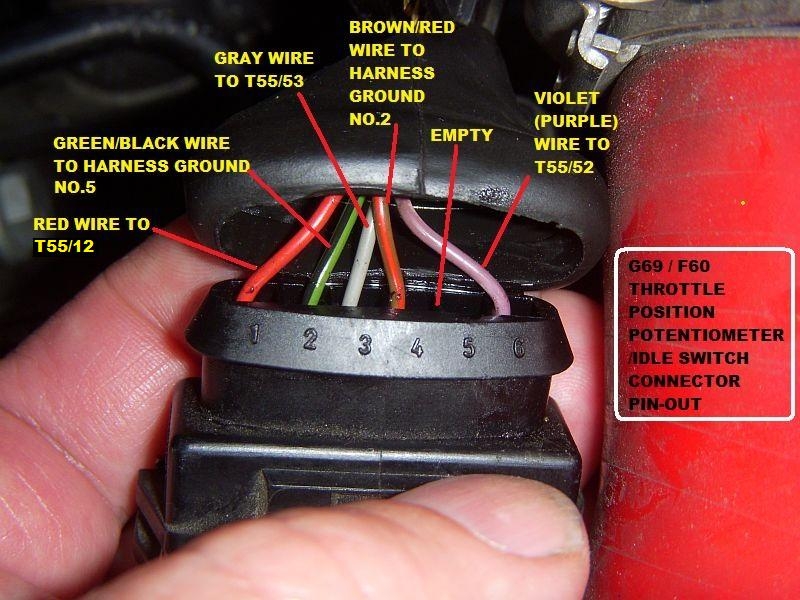
    The big one is the TPS, do someone know how the pins are connected?

    Also, i dont know where the smaller 2pin contact connects to, i guess its for the boost solenoid, everything contacts seems to be in matching colors, but this one is not?
    Contact is pure black, but boost solenoid is black and brown?
    I have no brown 2pin female contact at all.

    And also the vakum hooses/pipes, someone know what they (2 & 3) are for and where they should be conntected?

    No. 1, is it some kind of valve for backpressure?
    What does it do and the hoses/pipes do and what does it connect to?

    This is already cut:
    Injectors
    Cam sync
    Water temp on back of cylhead
    Airmassmeter
    lambdas
    ignition coils
    igition modules


    Vroom vroom!
    Last edited by Losgard; 22 November 2014, 22:59. Reason: Changed picture URL
    Vroom vroom
  • UrS4boy
    S2Forum Obsessed
    • Feb 2006
    • 11859
    • Country: Canada

    #2
    Originally posted by Losgard
    Im into putting a new ecu to it and cutting the old cables away
    New ECU like Motec or VEMS or Bosch Motronic? Cutting engine harness connectors, even for VEMS seems very very wrong.
    RS2'd 93 UrS4 5 spd sedan
    94 UrS4 V8 6 spd manual avant

    Comment

    • Losgard
      S2Forum Buff
      • Jun 2009
      • 41
      • Country: Sweden

      #3
      My new ecu is a maxxecu, i would like to do the flying lead myself, not using old cables or connectors.
      I dont really understand what you seems to be very very wrong? Explain for me please.
      Vroom vroom

      Comment

      • Losgard
        S2Forum Buff
        • Jun 2009
        • 41
        • Country: Sweden

        #4
        Maybe answered the question by myself about the 2pic connector, it may be the IAT, and its pretty near the TPS...
        But if thats the situation, theres another problem, i miss my 2pin boost solenoid contact.

        Maybe someone knows something about the pipes/hoses instead?
        Vroom vroom

        Comment

        • newsh
          S2Forum Obsessed
          • Aug 2003
          • 16226
          • Country: United Kingdom

          #5
          The boost solenoid connector is very close to the MAF connector down near the front of the air box behind the headlight. The one at the back of the bay, near the TPS is either the IAT, ISV or the solenoid valve for the carbon canister.


          Sent from my iPad using Tapatalk HD

          S2 Coupe 3B Project


          Ur quattro restoration

          S2 Avant

          Boost is the new rock and roll!
          sigpic

          Comment

          • UrS4boy
            S2Forum Obsessed
            • Feb 2006
            • 11859
            • Country: Canada

            #6
            Originally posted by Losgard
            My new ecu is a maxxecu, i would like to do the flying lead myself, not using old cables or connectors. I dont really understand what you seems to be very very wrong? Explain for me please.
            Personally, I don't think it would be necessary to go to all the work if your maxxecu used a Motronic-style T55 connector, even if you had to repin the connector to work with the maxxecu ECU.

            As for getting help from forum members here, just asking "which 2 pin connector is this?" won't get the answers you want. You need to at least provide some information about the colours of the two wires coming into the connector. Even more so with a 5 pin connector, etc.

            Here is a partial list of the 2 pin connectors used on in an ABY engine bay (there are at least 7 different devices that use a 2 pin connector in that engine bay)

            Attached Files
            RS2'd 93 UrS4 5 spd sedan
            94 UrS4 V8 6 spd manual avant

            Comment

            • Losgard
              S2Forum Buff
              • Jun 2009
              • 41
              • Country: Sweden

              #7
              URS4boy, my bad...
              I hate typing Swedish, Sngelish and German.
              The big 6pin connetor to TPS is only pluged in with 5 pins, i wondered if someoen know what the pins do.
              Got no color or nothing, i must check that tomorrow then, just though if someone that is good at doing ecu installing on theese engines would know.

              Im most interested in No. 1, 2 and 3 now.
              One pinky vacuum, from/to?
              One yellow vacuum, from/to?
              And a black/yellow BLOB with 2 outputs on the black side, but only one for the Yellow side. What does it came from, why does it separates and where do it go.
              Vroom vroom

              Comment

              • UrS4boy
                S2Forum Obsessed
                • Feb 2006
                • 11859
                • Country: Canada

                #8
                I don't get paid enough for this.

                Originally posted by Losgard
                The big 6pin connetor to TPS is only pluged in with 5 pins, i wondered if someoen know what the pins do. One pinky vacuum, from/to?
                One yellow vacuum, from/to?
                The pink (actually violet) hose is for the rear differential lock.:

                Diff lock info: http://forums.quattroworld.com/s4s6/msgs/170940.phtml

                There is a green vacuum boost hose that goes to the moisture trap and then the ECU:

                Moisture trap info: http://forums.quattroworld.com/s4s6/msgs/20401.phtml

                The Throttle switch wiring works like this (wire colours are AAN but the positions are the same for the ABY/ADU, etc.)

                G69 / F60 Throttle valve position potentiometer /idle switch information: http://forums.quattroworld.com/s4s6/msgs/20405.phtml

                AAN pin-out info so you can find out what pins T55/12, T55/52 and T55/53 are all about:
                The Audi Enthusiast website. Forums for all Audis including A4, S4, A5, S5, A6, S6, allroad, A8, S8, TT, R8, Q5, Q7, 4000, 100, 200, v6, v8, vintage, local forums


                Last edited by UrS4boy; 23 November 2014, 16:29.
                RS2'd 93 UrS4 5 spd sedan
                94 UrS4 V8 6 spd manual avant

                Comment

                • Losgard
                  S2Forum Buff
                  • Jun 2009
                  • 41
                  • Country: Sweden

                  #9
                  I didnt know what harness meant yesterday, now i know.
                  Someones like a adapter and continue running the old harness, some dont. I prefer not to.
                  Im about to cut the entire old harness out.
                  This 2 contacts is all cables/contacts thats left for ecu, and maybe the boost solenoid contact that havnt found yet.

                  Theres no big job if you just know where the connectors goes to, i think theres a bigger problem if the original harness starts to fail.
                  Theres is a motronic connector to buy, pinned and ready to connect to the cars motronic connector.
                  It looks pretty nice, but £330 for motronic connector if you buy it alone, i dont think it worth it, and theres no guarante you dont get a problem with the original harness in the future.
                  Theres no guarantee i dont get a problem with my new harness either, but then it will be less than a minute to locate the cable/contact that fails.


                  Thats a great picture, but its kind of a maze to go through wiring diagrams to know the positive and the signal.
                  I never used more than 3 cables to the TPS, -+ signal.
                  Thats why im confused by the 5 pins.

                  This is how it should be connected as far as i can se?
                  Im not sure about No.1 because PIN22 is OBD function, do you think this is correct?

                  No1, Positive?
                  No2, Ground
                  No3, Throttle position potentiometer (Throttle angle)
                  No4. Ground


                  Thank you all so far.
                  Vroom vroom

                  Comment

                  • newsh
                    S2Forum Obsessed
                    • Aug 2003
                    • 16226
                    • Country: United Kingdom

                    #10
                    TPS has 2 functions, a potentiometer (variable resistor= throttle angle) and a switch for idle (throttle closed switch)

                    S2 Coupe 3B Project


                    Ur quattro restoration

                    S2 Avant

                    Boost is the new rock and roll!
                    sigpic

                    Comment

                    • UrS4boy
                      S2Forum Obsessed
                      • Feb 2006
                      • 11859
                      • Country: Canada

                      #11
                      Originally posted by Losgard
                      This is how it should be connected as far as i can se?
                      Im not sure about No.1 because PIN22 is OBD function, do you think this is correct?

                      No1, Positive?
                      No2, Ground
                      No3, Throttle position potentiometer (Throttle angle)
                      No4. Ground


                      Apologies. The text in my throttle position switch post that I linked you to is correct. Turns out that the photo was incorrect (T55/22 for pin 1 instead of T55/12). I had not noticed my error until you flagged the T55/22 confusion. You were right to be confused. My bad. Sorry.

                      The text in my G69/F60 post (http://forums.quattroworld.com/s4s6/msgs/20405.phtml ) was correct and it said:

                      "Pin 1: A red wire that also connects to T12/55 in the ECU which provides 5V+ to the G69/F60 combination as well as the F96 Barometric Pressure Sensor and the G40 Cam Position sensor. (Note: The Bentley incorrectly calls the Pressure Sensor the "G16" but there is no such "G16" device for the AAN).

                      Pin 2: Green wire with a Black stripe - goes to ground connection 5 in the engine harness.

                      Pin 3: Gray wire connected to pin T53/55 in the ECU - the signal is the 5V+ modified by the variable resistor in the throttle position switch which tells the ECU the degree to which the throttle body is open, which helps the ECU compute "load".

                      Pin 4: Brown wire with a red stripe, goes to ground connection 2 in the engine harness.

                      Pin 5 - not used

                      Pin 6 - Violet (purple) wire that connects to pin T52/55 in the ECU that tells the ECU that the throttle is closed (via the microswitch in the diagram shown above)."

                      Here is the corrected photo:

                      RS2'd 93 UrS4 5 spd sedan
                      94 UrS4 V8 6 spd manual avant

                      Comment

                      • Losgard
                        S2Forum Buff
                        • Jun 2009
                        • 41
                        • Country: Sweden

                        #12
                        Thanks newsh, i didnt realise it need a switch for idle.
                        My new ecu only requier the resistance for fully closed and full open throttel.

                        In my last garage we was 7 people, i think someone stole some contacts or something. I know that in 3 cars they were doing some electricity work in.
                        Me and my garage buddies became enemys with the owner and his brother, cars scratched, stolen tools, made sabotage on a deck with a center punch etc.
                        Because, i cant find some connectors, the 2pin in the last pic belonged to the gearbox, a contact on the right side of it.
                        Now i know im missing either my boost solenoid contact or my intake air sensor.

                        I found another 2pin, its black plastic, the cables are yellow/black and purple/black.

                        Are the knock-sensors cables in a shielded isolation?
                        Because their in some more heavy isolation than the other cables, in one piece isolation all the way thru the big harness to the inside of the car.

                        UrS4boy, where do you find the wiring diagrams and pictures for everything?
                        Are you googleing or do you have some electric manual in pdf or something?
                        Im searching from time to time when im finding something i cant figure it out, but i dont think im doing it properly, i think im using the wrong terms or something.
                        It would be nice to solve this without asking for every single electric question.
                        Vroom vroom

                        Comment

                        • UrS4boy
                          S2Forum Obsessed
                          • Feb 2006
                          • 11859
                          • Country: Canada

                          #13
                          Originally posted by Losgard
                          UrS4boy, where do you find the wiring diagrams and pictures for everything? Are you googleing or do you have some electric manual in pdf or something?
                          For UrS4 stuff I use this 93 UrS4 AAN wiring pdf:


                          For the times I am trying to include S2 ABY or RS2 ADU wiring info into my AAN-based engine bay device posts, I use Paul N.'s S2Central.net info:


                          Then Technical Data

                          Then Electrical Systems

                          Then Wiring and Schematics

                          Then RS2 ADU (S2 ABY is not populated yet -ADU wiring is probably identical considering that the RS2 is really a very very nice S2 Avant)

                          Then the sheet as appropriate, e.g. Sheet 12 - Motronic, fuel injectors, MAF

                          If you right click on the sheet name and open in a separate window you can a) print it and b) use the link to post it up here, like these:


                          RS2'd 93 UrS4 5 spd sedan
                          94 UrS4 V8 6 spd manual avant

                          Comment

                          • UrS4boy
                            S2Forum Obsessed
                            • Feb 2006
                            • 11859
                            • Country: Canada

                            #14
                            Originally posted by Losgard
                            Now i know im missing either my boost solenoid contact or my intake air sensor. I found another 2pin, its black plastic, the cables are yellow/black and purple/black.
                            I think you found the G42 ABY/ADU air intake temp sensor, on tracks 20 and 21, with the yellow/black connected to pin T55/44 of the Motronic ECU:

                            RS2'd 93 UrS4 5 spd sedan
                            94 UrS4 V8 6 spd manual avant

                            Comment

                            • Losgard
                              S2Forum Buff
                              • Jun 2009
                              • 41
                              • Country: Sweden

                              #15
                              Thats nice, so that one can be cutted away to.
                              Before i cut the cables i put tape with name on for what it connects to, those i didnt tape was because i didnt know what they connects to. Therefor they are still untuched, like this one.
                              Im 100% sure ive not cutted boost solenoid myself, i dont have any un-marked cables and connectors in my crap bag.

                              I guess its no problem, because i still would have cutted them, at the same time it bothers me someone else has has stolen more things belonging to my car, more than i already knew.

                              Great links UrS4boy, i think the most will be solved with the help from the diagrams, even if it will take a year to find and match cable colors to a sensor.
                              Vroom vroom

                              Comment

                              Working...