You can change the style the forum displays by selecting your preferred style at the bottom left of the site.
We have made an enhancement so that old threads should now link from search results to the correct thread. This is not yet in place for single post links
Well the marks are relative to the viewing window not the "vertical" 0 degree position.
The point is the ECU needs to see the firing trigger X degrees before cyl 1 reaches TDC.
Panthero Coupé quattro 20vt
Indigo ABY coupé
Imola B6 S4 Avant
I stand by the HEX theory for now... see attached... imagine a counter that increments on the +ve edge of flywheel teeth detected after the passing of G4 - that yields 36.75 teeth to the timing mark which is exactly 98 degrees - which is exactly 62 in HEX.
If its not true then its one wonderful co-incidence.
And here is a pic with flywheel perched onto input shaft of the gearbox and the timing marks aligned. By my measurements the angle between the G4 sensor window and the timing mark is more like 73 degrees - far away from the mythical 62.
I was thinking maybe there was some parallax errors due to photo from a distance but the angle from timing mark to G4 sensor is pretty well bang on 98 degrees so I am standing by my 62h theory.
I think this is quite a revelation - I shall reward myself with a cold beer and raise a stein to German Dilbert who has been laughing at us all these years.
From what I've read in the replies above I'm correct on the G4 timing pin position it's just the other two pins on the opposite side of the flywheel to the G4 pin that I'm wondering about now, are these needed and if so why are they there?
The other 2 pins are not needed for the engine to run.
Don't forget, when the timing mark is indicating TDC, the timing pin has already passed the sensor. The sensor reads X degrees BTDC, not coincident with it
The relationship between the mark and the pin is irrelevant unless you factor in the relationship between the window and the sensor location
Panthero Coupé quattro 20vt
Indigo ABY coupé
Imola B6 S4 Avant
Don't forget, when the timing mark is indicating TDC, the timing pin has already passed the sensor. The sensor reads X degrees BTDC, not coincident with it
The relationship between the mark and the pin is irrelevant unless you factor in the relationship between the window and the sensor location
Alex - thats all fully understood. The confusion has been how all the Audi 20VT docs since time immemorial have stipulated 62 deg between G4 and TDC on #1 when we can clearly see its actually 98 degrees. Assuming there might be an offset in the viewing window (which I don't agree with as it is declared in docs as for the TDC mark for #1) then I drew this up.
Because of the alleged 36 degree difference it got me wondering does the timing mark actually align with any cylinders being at TDC.
Whilst we can consider the timing marks to be no more than a safe and convenient assembly aid for engine building, it would be very odd not to have such a reference mark align with #1. But we know its an oddball engine as the crank locking tools do not engage while timing marks are aligned. I think I need another beer to calm me down.
If I can see the G4 timing pin from the angle that you are showing, you have the flywheel on backwards if that impacts anything that you are saying.
Just sayin'.
I've got a spare AAN on a stand but I am going away and doubt that I can play with things until I get back on Tues or so. I would take the spare plugs out and rotate the engine until I have No.1 at TDC with the cam timing mark lined up as close as possible. I would determine TDC by having a chop-stick or dowel in the No.1 spark hole and noting when it peaked in height.
RS2'd 93 UrS4 5 spd sedan
94 UrS4 V8 6 spd manual avant
No - its not on backwards... Maybe I didn't explain well how i took the photo with flywheel sitting inside the bell housing, but it would be impossible to mount it backwards.
My flywheel has the clutch still attached, so I presented it all (heavy big brute that it is) to the input shaft on the gear box with the spring plate going in first if that makes sense... I know it started to engage on the release bearing as a bit of clutch fluid squirted out the slave cylinder.
The fly wheel bolts that you can see are the threaded ends which screw into the crankshaft. Look at the photo as if you are the crankshaft - turning clockwise, with the reference marks at approx 1 o'clock and the G4 sensor window at approx 4 o'clock.
Will you now subscribe to my 62 degree hexadecimal theory of accidental mechanics ?
Seriously though - need to see engine pics with the head off while the reference marks are aligned to verify where Cyl #1 sits at that point.
My engine is also on a stand that mounts from flywheel end so its impossible to attach the flywheel and align anything without the gearbox in place.
So who in their right mind designs an engine where you cannot verify the crankshaft position unless the gearbox is attached ? There is some alignment marks on the oil pump end I know, but who knows how accurate they are.
Originally posted by UrS4boy
If I can see the G4 timing pin from the angle that you are showing, you have the flywheel on backwards if that impacts anything that you are saying.
Just sayin'.
I've got a spare AAN on a stand but I am going away and doubt that I can play with things until I get back on Tues or so. I would take the spare plugs out and rotate the engine until I have No.1 at TDC with the cam timing mark lined up as close as possible. I would determine TDC by having a chop-stick or dowel in the No.1 spark hole and noting when it peaked in height.
If you are referencing TBC to the viewing window on the bell housing, then you need to reference the timing pin with relation to the G4 sensor.
When the TDC mark on the flywheel aligns with the viewing G4 sensor window, the timing pin is already "62°" past the G4 sensor. The G4 sensor is X degrees of crank rotation from the viewing window, on this drawing 98° minus the timing 62° offset.
See my childish crayon drawing:
As before I am still convinced the factory data is wrong and actual firing trigger is actually ~ 58° BTDC
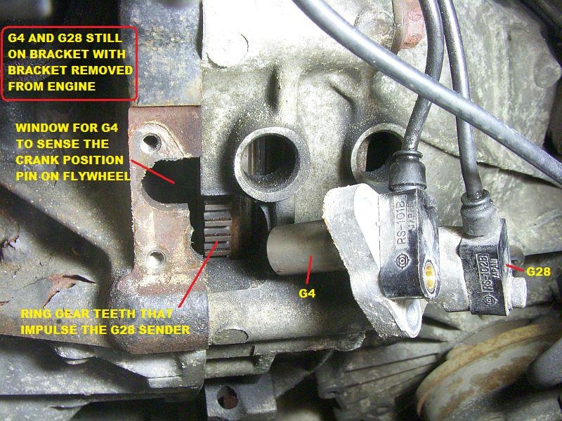
But the G4 sensor window is not where you marked it up in red - it is approx 73 deg before the timing mark - see one of the drawings I did where I pointed to position of G4 sensor on the bellhousing.
You marked the position up wrong
It's not as far away as you think. The G4 is located virtually in line with the two holed bosses on the bell housing approx 40 degrees from the timing window.
We process personal data about users of our site, through the use of cookies and other technologies, to deliver our services, personalize advertising, and to analyze site activity. We may share certain information about our users with our advertising and analytics partners. For additional details, refer to our Privacy Policy.
By clicking "I AGREE" below, you agree to our Privacy Policy and our personal data processing and cookie practices as described therein. You also acknowledge that this forum may be hosted outside your country and you consent to the collection, storage, and processing of your data in the country where this forum is hosted.


 Maybe I didn't explain well how i took the photo with flywheel sitting inside the bell housing, but it would be impossible to mount it backwards.
 ?
?
Comment