You can change the style the forum displays by selecting your preferred style at the bottom left of the site.
We have made an enhancement so that old threads should now link from search results to the correct thread. This is not yet in place for single post links
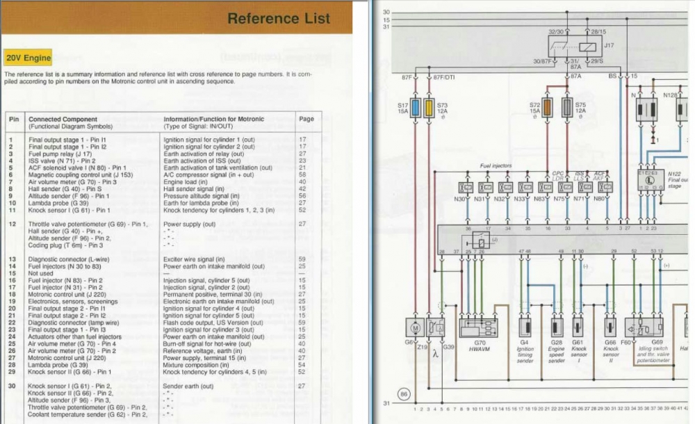
So are you guys saying that 87a will power pin 37 or do I need to splice something directly into pin 37? Like the protected side of ignition fuse to pin 37? And pin2 of the hall sender is exceed 5v for sure.
I guess English is not your first language because your reading comprehension is poor.
I say what I have said before: Pin 37 needs to get power from the same exact line as the fused line from 87A that feeds the injectors power.
Ok, have some goods and some odd news. I am getting 11.5v switched power at pin 27 so thats all set. But the odd thing is when I have the ECU connected and when I just have the key turned on and NOT cranking I still get 11.5 volts at the fuel injector connectors. And pin2 of the hall sender is exceeding 5v for sure its in 10v range. Any thoughts?
Last edited by Durr McDanks; 27 January 2011, 03:01.
Yes but it freaked me out when I first saw 87a being held at 12V inside the FP relay after shutdown - courtesy of MAF afterburn sequence and the ECU holding pin 37 at 12V... By this I mean that you should not really consider ECU pin 37 to be an input - though I have never tried on the bench to isolate it and see what the effect is on happiness of ECU s/w or h/w.
Sorry - I wasnt explicit there but I meant FP pin 87a is only at 12V when the engine is running/cranking - i.e the relay is energised by ECU. We are saying the same thing...
Paul: I just wanted you (and me) to be clear on 87A and its relationship to Pin 37. Mr. McDanks seems to have problem grasping the need to power Pin 37 as shown in the AAN diagram, i.e. through the exact same source as the power to the injectors.
Sorry - I wasnt explicit there but I meant FP pin 87a is only at 12V when the engine is running/cranking - i.e the relay is energised by ECU. We are saying the same thing...
The FPR gets energized by pin 3 of the AAN ECU correct? What I was saying about the Hall sender connector is that one pin is getting 5 v like it should but the pin thats goes to the ECU gets 10v? Just doesnt seem normal to me.
Sorry - I wasnt explicit there but I meant FP pin 87a is only at 12V when the engine is running/cranking - i.e the relay is energised by ECU. We are saying the same thing...
Just remember you will only see +12V at pin 37 when the engine is cranking/running... then after shutdown the ECU holds this pin at 12V for a few moments as part of the 'afterburn' pulse on the MAF - used to clean any deposits etc from the hotwire. I always thought it weird that Audi wired it this way, but there you are.
Paul: Sorry, but I do not agree with you about Pin 37 only getting power while cranking. Pin 37 is fed from the FP relay pin 87A, through a fuse, and after the injector power wires (N30, 31, 32, 33 and 83). As a result, it is powered all the time that the FP relay is energized, not just while cranking:
Ok, but regarding pin 27 when you talk hooking up the protected side of the IGNITION fuse to all the 12v inputs isnt that already done within the wiring harness? I just dont get it because when I look at the AAN wiring diagrams that protected side wire is "T3w/2 for Ignition Coil 5 (N164)" so why would I be hooking coil 5 to the other coils then pin 27? Sorry just wondering/ confused.
One more question about the cam position sensor or hall sender(not in the AAN case). On the connector, I know one of the pins gets 5v but my other pin is getting around 10v is this normal?
Last edited by Durr McDanks; 26 January 2011, 12:04.
Sounds like you should be OK (hard to be completely certain sitting here though) - but see my comments on Pin 37 above so you don't get confused when you just turn on the key. To be more clear :
Pin 18 is permanent 12V
Pin 27 is 12V when key is ON
Pin 37 is 12V ONLY when engine is cranking (then momentarily held there by internal ECU relay for afterburn)
Ok, thank you.
Questionsall information comes from this thread on page one: http://www.s2forum.com/forum/showthread.php?t=38722)
Pin 27: I have that black wire(B 15) from black terminal B of the b3 90 fusebox hooked up to black wire of the AAN S115 ignition coil fuse which in the AAN case is a 15 amp fuse. By protected side you mean "Black/Green (4.0) T3w/2 for Ignition Coil 5 (N164)" correct? So your saying to hook up the black/green wire from fuse S115 to pin 27 then?
Pin 37:
So all your saying is that if I have 87a hooked up to, in my case, both the blue "unprotected side" of S116(fuel injectors fuse) and s75(WGV etc.) then pin 37 is good?
Just remember you will only see +12V at pin 37 when the engine is cranking/running... then after shutdown the ECU holds this pin at 12V for a few moments as part of the 'afterburn' pulse on the MAF - used to clean any deposits etc from the hotwire. I always thought it weird that Audi wired it this way, but there you are.
From early B3 fusebox, you need to add some extra fuses to support S2/RS2 wiring. For this reason it is easier to do conversion with ABY or ADU loom instead on AAN, but we can work round this.
Pin#27
On the B3 fusebox is large multipin connector (black in colour from memory) that plugs into a socket labelled 'B' - find that and there should be black wire on the 'B15' pin - check it goes to 12V when ignition is on. Use this pin to feed into a 20A fuse - this would be Fuse 32 on an S2... Take the protected side of Fuse 32 and hook up to the 12V inputs to the coilpacks and also into pin 27 of the ECU.
Pin #37
This one has some complexity behind the scenes but I will avoid that here for now. Ensure that pin #37 from the ECU connects (usually on black/blue wire) to the common side of all the fuel injectors and the MAF (pin 5). The source of this signal is another auxiliary fuse (Fuse 28 on S2/RS2) which connects to terminal '87a' on the B3 fusebox - this is a fuel pump relay output. Note you should have Fuse 24 also connected to '87a' which protects the 12V supply into EVAP, ISV, WGFV and afterrun relay.
Ok, let me put it this way then. How would you supply power to AAN ECU pin 27 and 37 with a b3 90q fusebox? I understand they need to be switched sources.
We process personal data about users of our site, through the use of cookies and other technologies, to deliver our services, personalize advertising, and to analyze site activity. We may share certain information about our users with our advertising and analytics partners. For additional details, refer to our Privacy Policy.
By clicking "I AGREE" below, you agree to our Privacy Policy and our personal data processing and cookie practices as described therein. You also acknowledge that this forum may be hosted outside your country and you consent to the collection, storage, and processing of your data in the country where this forum is hosted.
 all information comes from this thread on page one:
Leave a comment: