
Might be worth posting another thread about a specific fault to get a wider spread of members experience.
Do you know whether the vehicle has been modified, i.e. chipped? If so do you know the origins?
Has that altitude sensor value changed to something more accurate? I don't think it makes a massive difference unless of course as mentioned previously it is acting as that towing power limiting function. The value was suspiciously close to the published one!
-
Good that it could be of any use.
I've now got the car running and everything seems to be fine. I have the same problems with hesitation during WOT once I get turboboost.
Since this is not related to the topic I made a new thread here so this is not mixed
Last edited by minim; 17 August 2013, 11:53.Leave a comment:
-
Your photo was too good to pass up so I "stole" it and used in this:
UrS C4, 200 20VT (3B) and S2/RS2 OBD1 Fault Code access port locations and info:

"Here is a set of RS2 diagnostic plugs in the fuse box hooked up to a RossTech VAG-Com via a 2 x 2 adapter:
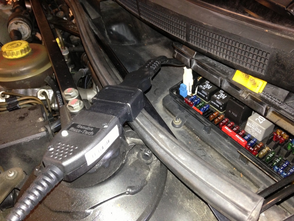
Photo courtesy of minim on the S2 Forum"Leave a comment:
-
Based on recent evidence, I am not convinced of this. Needs more/better photos of the same ADU head taken at the same time both from the front and the rear showing the position of the cam timing marks and the cam sprocket with the G40 Hall sender shutter (without moving anything).
AFAIK, the cam timing marks O-O are used to sync the cams, not necessarily at TDC. Once the chain is on and they are sync'd together, it doesn't matter too much whether that wasn't the crank-to-cam timing position.Leave a comment:
-
Well they don't and there's nothing I can do about it with these parts. They do not align up until the cam pulley is about one tooth out. The position of the exhaust cam "O" marking is fixed as the cam pulley must be fit at the key hole that is into the exhaust cam. At TDC the exhaust cam is not aligned against the edge of the head so I have to move it about one tooth (on cam pulley for cambelt) out of position to get the exhaust cam "O" aligned with the edge of the head and when that is aligned the intake is also aligned.
I've now gone trough AAN workshop manual and what it says about camshafts installation. When installing cams the only thing they are talking about is aligning the two "O" marks at the edge. I'm not sure but from what I read there the aligning of the "O" marks doesn't have to be at TDC so it might actually be correct. At least there's nothing I can do to change this as the cam pulley is at a fixed position and as long as both line up at the edge I can't really change anything for the better.Leave a comment:
-
With the crankshaft set at TDC, the cam pulley set half a tooth as needed on ADU and the markings on the chain sprockets should then line up perfectly.Leave a comment:
-
Leave a comment:
-
Minim: This is the way the cams are supposed to line up. If they don't you need to mark them, remove them (at least one, e.g. the exhaust cam) and rotate the cam by one tooth (as needed) and then re-install and check again.

Leave a comment:
-
Comparing again... wtf's up here The picture attached by UrS4boy on the left side and mine on the right. The angle the photography is taken from on these two pictures are not that different and still.. on mine I can't see a mark on the pulley and on UrS4boy's picture I'm sure I see a mark. Do you happend to have a better quality on that picture UrS4boy so I could zoom and compare?

Leave a comment:
-
Ouch. What I see there scares me a bit. If you look closely the mark on the pulley is at the edge there when the O's are lined up. Mine is one tooth down when the O's are lined up. There is nothing I can do about this issue except changing my exhaust cam, but I did measure it and it had the correct lift for ADU so..
Edit: after looking a bit more on it I think the picture is taken from a angle that makes it look like the mark on the pulley is at the endge but it's actually below the edge.
After some more thinking tho I can't understand how I could set them to get this better. The O at the exhaust mark isn't lined up with the edge of the top before exhaust and inlet cams are lined up. This means that I can't get it any better than it is. I cannot move the pulley on the exhaust cam so this means I can't set it anywhere else to get things lined up... I'm just going to put it back together as it is now as this must be correct with the parts I've got.Leave a comment:
-
The comment I made was for the OP!
Still trying to fathom what you are going on about! Lets sort this out and then if necessary start a new thread.Leave a comment:
-
I see that but it doesn't deal with the compensating rotations that I think are occuring.
Hard to do this remotely without the physical in front of you.
The photo I presented in post 21 is not mine. Unfortunately it's cockeye'd relative to the top of the head, making "accurate" assessments difficult. Here it is again with some annotations:
Leave a comment:
-
Look at the first pic in post 21. The only other issue is perhaps the timing chain has stretched.Leave a comment:
-
Okay, my head is officially going to explode. (Please help me!!)
I did a better rotation of minim's RS2 ADU 034109195B cam sprocket and now I don't like what I see. Hopefully, I am just confused. See below.
First, we start with the AAN sprocket again. Note where the lines between teeth 6 and 32 and 1 and 27 strike the shutter wheel relative to the shutter wheel opening.
Now look at the revised annotation of the ADU 105B sprocket. It appears to me that the ADU shutter wheel opening location is rotated one tooth (= 6.92 degrees (= 360/52) relative to the lcoation of the AAN shutter wheel opening (using the 6-32 and 1-27 lines as reference points). Where my head wants to explode is the ad hoc adjustment of the ADU sprocket about one tooth to the left (anticlockwise from the front or clockwise to from the rear). This means that ADU exhaust cam lobes are brought back to the same location as the AAN cam. WTF??
 (Hopefully I am just confused)
Leave a comment:
-
An alternative way to look at this is that you have not changed the relationship between the camshafts or the engine timing. All you have done by using the correct pulley is to put the hall sensor rotor back to the correct position for the RS2 which we are hoping cures some of your issues. Therefore you have not changed the physical timing during all this.
Even those dots on the cams are not that accurate because even when you align them they shift during tightening the camshaft caps. There are some pics on here somewhere. Unfortunately its all rather unsatisfactory and not very precise.Leave a comment:


Leave a comment: