Swapping front hubs for more caster?

Collapse
X
 
  • Time
  • Show
Clear All
new posts

  • Error404
    replied
    It raises the roll centre, so increases the resistance to body roll


    So by lowering the car you are lower the centre of gravity, but you have also lowered the roll centre.
    By then raising the roll centre back up you make the most of the lower CoG

    Leave a comment:


  • Ryss
    replied
    Would some one mind explaining what impact on handing, this ball joint extension has. I understand that it keeps the control arm horizontal, with heavily lowered suspension.

    Is the position of the pivot centre (ball joint) critical. What effect would a spacer between control arm and ball joint have on handling, while keeping the control arm horizontal?

    No need to go too deep into the theory, but would appreciate an explanation that a layman can understand. Thanks.

    Leave a comment:


  • Audi_CQ
    replied
    Originally posted by Mr.Crossfire
    Thanks for the offer. Putting them on a car with slicks would be indeed a proper test. The problem is, that I don't have any prototypes ready yet. I don't want to have the production series made before testing, because if something fails, I have then 2500e worth of junk metal... I have 2pcs half-made with my own milling machine, but not yet complete. It is very slow to make with manual controlled machine & hard material. And I'm not a professional machinist either. But when I got some prototypes available, I will give info then.
    OK. Need both front and rear. Easier then moving inner side of wishbones upwards and I'm a bit lazy

    Leave a comment:


  • 4WheelDrifter
    replied
    Let us know when the prototype is made, and then tested by Roger.

    Leave a comment:


  • Mr.Crossfire
    replied
    Thanks for the offer. Putting them on a car with slicks would be indeed a proper test. The problem is, that I don't have any prototypes ready yet. I don't want to have the production series made before testing, because if something fails, I have then 2500e worth of junk metal... I have 2pcs half-made with my own milling machine, but not yet complete. It is very slow to make with manual controlled machine & hard material. And I'm not a professional machinist either. But when I got some prototypes available, I will give info then.

    Leave a comment:


  • Audi_CQ
    replied
    Originally posted by Mr.Crossfire
    Yes, I will. The best price I have got so far is such that I could sell those out for ~260e / pair + shipping fees. If there is enough people interested, I can go ahead and have them made. But of course I still have to test them first.
    When can you deliver? First trackday is end of May....
    If you need test person I'll do it . Powerful car on slicks should test them properly

    Leave a comment:


  • Mr.Crossfire
    replied
    Yes, I will. The best price I have got so far is such that I could sell those out for ~260e / pair + shipping fees. If there is enough people interested, I can go ahead and have them made. But of course I still have to test them first.

    Leave a comment:


  • 90quattrocoupe
    replied
    Originally posted by Mr.Crossfire
    The balljoint extender I desinged, looks like this:


    That's a prototype version I made out of a chunk of aluminium.
    It fits like this:


    The brake disc in the pic is a b5 s4 321mm, which has been turned down to 314mm to fit with the calipers. Anyway, with that extender one could easily use a8 323mm discs for example, even they are ~10mm deeper than the b5 discs. Now some chinese will propably copy the design of that extender as I published the pics. The final product will feature an radiused groove just below the axle stub that goes in the hub carrier, to eliminate stress fracture starting point. The angled surface is designed to be large, so that it would take support from the hub carrier, if/when there is a load that would be bending the extender.

    I have been thinking to have a small batch of these made, but first I'd like to test them in real life myself. And I have not gotten a sensible price for those, as it is somewhat tricky to machine + the hard material.
    Well, when you are done testing, let us know. I am sure there would be a few of us interested in purchasing some.

    Greg W.

    Leave a comment:


  • GT500
    replied
    Good work G60.

    I do hope those arn't stainless bolts?

    Leave a comment:


  • Mr.Crossfire
    replied
    Sure. Here's the finished setup:


    I went to extremes, because it needed to be done. It's a little annoying that there are now holes in the plate separating engine bay from the cabin air intake, so in some situations gasoline & oil smell is coming to the cabin. It is not a problem when driving normal speed, but I have to think some way to block it anyway. I measured the casters with my 4-wheel alignment system, and one side was little bit over 9deg and the other was little under IIRC. However, there is adjustment ability made to compensate that. The adjustment plates are bit ugly, because they're prototypes made by hand tools as my milling machine was broken But I had those laser cut afterwards, so now they are neat.

    The balljoint extender I desinged, looks like this:


    That's a prototype version I made out of a chunk of aluminium.
    It fits like this:


    The brake disc in the pic is a b5 s4 321mm, which has been turned down to 314mm to fit with the calipers. Anyway, with that extender one could easily use a8 323mm discs for example, even they are ~10mm deeper than the b5 discs. Now some chinese will propably copy the design of that extender as I published the pics. The final product will feature an radiused groove just below the axle stub that goes in the hub carrier, to eliminate stress fracture starting point. The angled surface is designed to be large, so that it would take support from the hub carrier, if/when there is a load that would be bending the extender.

    I have been thinking to have a small batch of these made, but first I'd like to test them in real life myself. And I have not gotten a sensible price for those, as it is somewhat tricky to machine + the hard material.

    Leave a comment:


  • macspring
    replied
    Originally posted by Mr.Crossfire
    I cut off the tops of suspension towers from my 90q and welded on adjustable plates which I designed. As a result I run now around 9deg of caster. Haven't noticed any real downsides yet. I am not sure if the rear inner wheel lifts at tight curves, I guess not but that might be just the spongy chassis. Those rally cars have cages so the chassis is much stiffer and could indeed lift the wheel. Anyway, I now have the V8 rear torsen-diff installed also, so it should help if there is wheel lifting.

    About the lower balljoint extenders, A friend of mine did some FEM on an extender setup which I had designed and there seems to be no serious issues with the strength. I will be manufacturing them from 42crmo4 which is ~equivalent of the AISI 4340, so considerably stronger than normal steel. Also designed it so that it will clear the brakes.
    Any Photos ?

    Leave a comment:


  • Mr.Crossfire
    replied
    I cut off the tops of suspension towers from my 90q and welded on adjustable plates which I designed. As a result I run now around 9deg of caster. Haven't noticed any real downsides yet. I am not sure if the rear inner wheel lifts at tight curves, I guess not but that might be just the spongy chassis. Those rally cars have cages so the chassis is much stiffer and could indeed lift the wheel. Anyway, I now have the V8 rear torsen-diff installed also, so it should help if there is wheel lifting.
    About the lower balljoint extenders, A friend of mine did some FEM on an extender setup which I had designed and there seems to be no serious issues with the strength. I will be manufacturing them from 42crmo4 which is ~equivalent of the AISI 4340, so considerably stronger than normal steel. Also designed it so that it will clear the brakes.

    Leave a comment:


  • G60Rallye
    replied
    They are filed 5mm forwards but they can be swung a lot more than that to get them even further forwards. They get the wheel as far forwards as I would want to run without getting issues with the wheel hitting the front chassis and bad shaft angles. I shall be getting them torqued up nicely!

    Leave a comment:


  • Error404
    replied
    5mm should give you about 0.5deg IIRC so well worth a bit of work with the file
    As a side note, I found I did get some ball joint slip with a nut and washer arrangement like you have mocked up there. I went back to the OEM ridged nuts and bollocked them up to 80nm All ok now

    Leave a comment:


  • G60Rallye
    replied
    I think the best way to sort that issue out would be to make a tubular front subframe and move the wishbone mounts higher up. I dont think it would take much doing to make a new subframe might look at making up a jig some time.

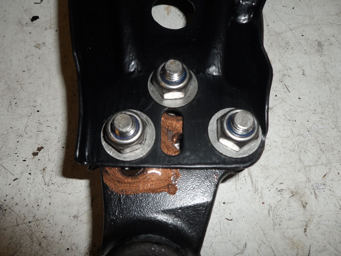
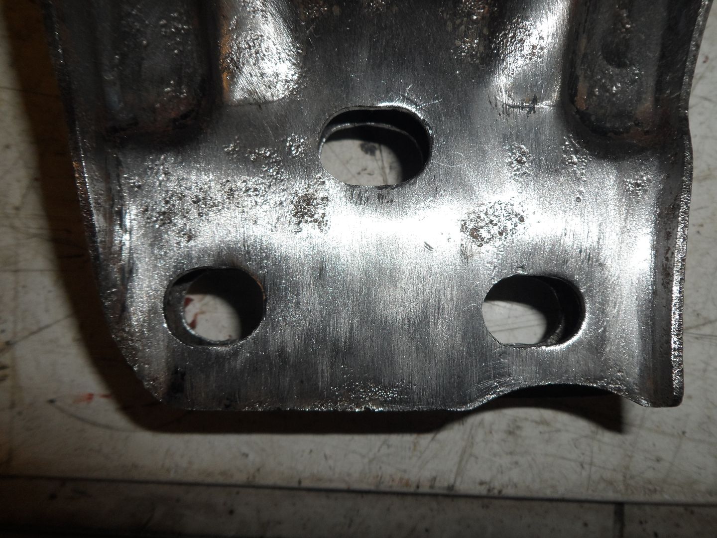
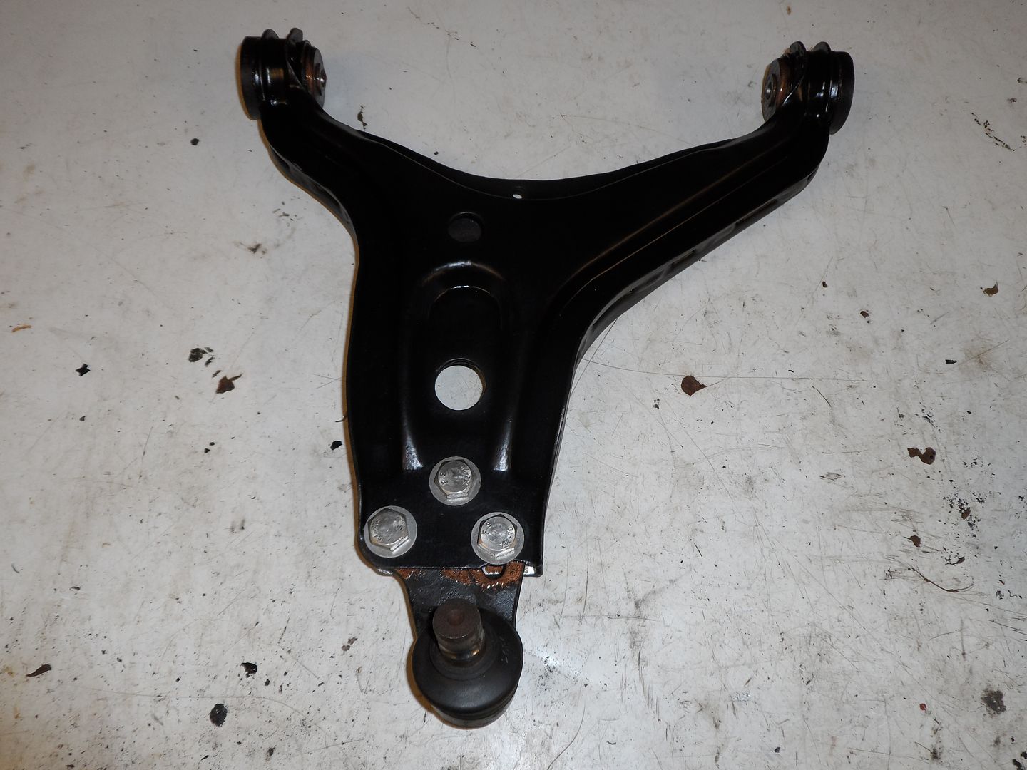
    Going back to the original subject with the caster. I swapped the hubs back over after all the discussion. I tried swapping the ball joints over, there is no future in that. It gives way too much to work with the arches and the shaft angles would be horrible!

    So I came up with another idea to get a little movement. Whilst cleaning up the wishbones I thought why not file the holes out a bit so the ball joints can be moved forwards and also pulled at an angle. I ended up going 5mm. This gives as much movement on the ball joint as I would want with shaft angles and space in the wheel arch.


    Leave a comment:

Working...