You can change the style the forum displays by selecting your preferred style at the bottom left of the site.
We have made an enhancement so that old threads should now link from search results to the correct thread. This is not yet in place for single post links
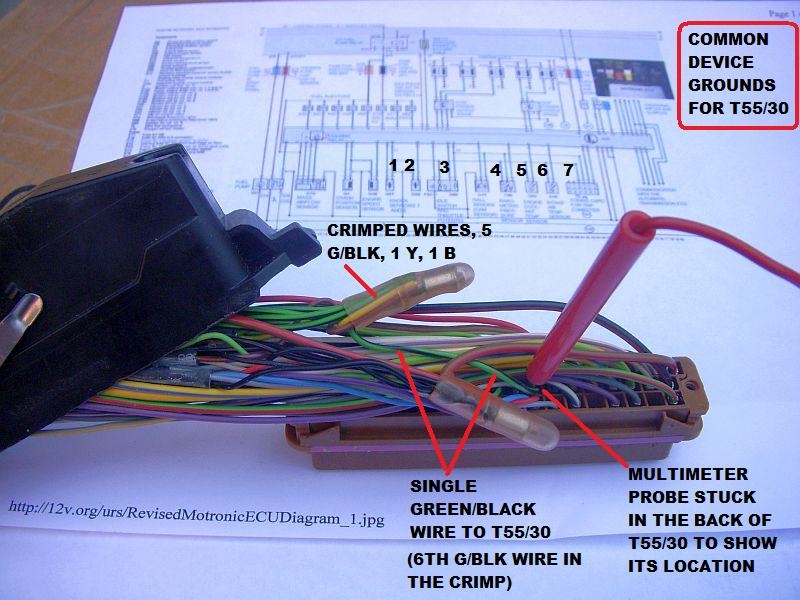
Removing Pins From the T55 ECU connector (for future reference)
Originally posted by gmac78
Cheers for that Paul, yeh hoping something is a miss inside the ECU connector, these wires felt quite stretched when i was putting it back together. It certainly didn't go back together as neat as it was when i first opened it.
Not sure if this is going to help or not:
Removing Pins From the T55 ECU connector (for future reference):
The Audi Enthusiast website. Forums for all Audis including A4, S4, A5, S5, A6, S6, allroad, A8, S8, TT, R8, Q5, Q7, 4000, 100, 200, v6, v8, vintage, local forums
Cheers for that Paul, yeh hoping something is a miss inside the ECU connector, these wires felt quite stretched when i was putting it back together. It certainly didn't go back together as neat as it was when i first opened it.
That pdf will give you a sense of what things are bundled in each branch of the ABY loom if looking for shorts but yours is a converted 3B loom so you may need to investigate further.
Hopefully you will see something obviously amiss when you open the hood on that ECU connector.
It is massively easier with a breakout box but with patience you should be able to do it the hard way one pin at a time. Also have a real good look that some insulation on the pins is not exposed to each other... It's very tight in there as you know.
Grab a notepad (or spreadsheet is even better) and tackle a handful of pins at a time - note where they should be going and write down what you observe with a multimeter.
I guess your right Paul, Going back through all the ECU pins and checking that they are indeed in the correct place is something i should do. I've been putting off opening up the ECU wiring connector due to how awkward it was to move these pins about. Getting the last few pins removed and transferred was a bit of a mission but needs must i guess.
If i had pins inserted in the wrong location would there not be a fault code continually present? Perhaps not?
Going back to 3B Pin 2 at potential related issues:
T55/2 Return signal path (ground) for several components: Air Temp, coolant temp sensors, Knock 1 and Knock 2 sensors, altitude sensor, throttle position sensor(White/Black stripe wire)
(ECU terminal 2 is also connected to terminal 30 on ECU via harness welded connection)
You threw me there by referencing "Terminal 30" which I instinctively read to mean permanent 12V but then I realise you are talking about ECU terminals - I prefer to call them "pins" for the avoidance of doubt but no bother.
Pin 30 is the 0V reference point for the 5V supply created by ECU for the TPS, F96, G40 etc - it is not a general purpose earth or 0V pin.
If it was me, I would take the time with a breakout box to buzz out every pins connectivity to its correct destination or 12V or 0V. Rectify anything that uncovers and try connectivity between critical pins to other / bad locations which might find a short somewhere.
Next on the list would be an oscilloscope on to G4, G28 and G40. I posted already what those signals should look like but it need a forum search to dig them up.
If those look good (also injectors and coils are being triggered in the correct order) then it's time to try a different ECU !
Thanks very much for all the help guys, very much appreciated. I'm heading offshore today but only for a week so will be back soon enough to continue with the saga.
The car has had so much work done recently that the issue is not so easy to narrow down. I've always had my suspicions about the ECU as the TV repair man that carried out the work was kind of moaning about how awkward it was to remove the old resistor in order to fit the correct R201. Something about the solder been high temp and having to put a lot of heat into it to get it to flow. He did mention he was worried that he might damage a track due to the heat but said that he reckoned it went ok in the end.
He was showing me the soldered R201 afterwards and it wasn't the prettiest job but these resistors are very small and smaller than what he normally deals with inside TV's etc.
Anyhow, the ECU may very well be ok so don't want to go accusing him of anything. Just seems like a lot of electrical gremlins have been plaguing me since getting the ECU back from the TV guy following the correct resistors been fitted.
I guess what i really need is another ABY ECU set up to run RS2 spec, with or without chips since i already have these just to see how the car performs with regard to boost, IAT etc etc. Certainly the way the car runs at the moment just doesn't feel any different to the previous homefry.
There is a lad local to me the that has an ABY down a field rotting away. I have tried to purchase it off him for spares but he's not playing the game. I could try and chase him down to see if i could borrow his ECU which is set up for normal homefry i think just to start the car briefly and see what the IAT do.
Would this be acceptable just to start the car and let it idle, no driving?
Failing that i do have TS Tuning chips i could try, should i try these instead of getting Paul " S2 Central" to burn me a set of standard RS2 software?
One other thing to note is the car sometimes stalls when you come off throttle and coasting to a stop. It never did that before. Also the VSS fault code that i was getting the other day only showed it's ugly head for one day and never reappeared. Something fishy going on!!
If there's anything you want me to measure on mine then let me know. I'll be back home on Sunday.
I know if I run TS chips on mine I get too much boost, owing to the gt30 turbo, so I'm running an eBoost controller set to 1.5 Bar and the car is pretty ferocious.
Going back to 3B Pin 2 at potential related issues:
T55/2 Return signal path (ground) for several components: Air Temp, coolant temp sensors, Knock 1 and Knock 2 sensors, altitude sensor, throttle position sensor(White/Black stripe wire)
(ECU terminal 2 is also connected to terminal 30 on ECU via harness welded connection)
I'm confused with this one guys, any ideas?Thanks Gordon
When the G42 IAT fails or it is removed from the system, as shown before, the ECU assumes 40 deg C. That is about 550 ohms resistance.
The 3B G42 is connected to Pin 44 of the ECU with a black/yellow and a ground connection in the harness with a black/violet wire. This ground ends up at ECU pin T55/30. Should be the same for a 3B or ABY/ADU
The seven devices are, left to right,
1. G61 knock sensor, 2. G66 knock sensor, 3. Idle switch/throttle potentiometer, 4. F96 Altitude sensor, 5. G62 engine coolant temp sensor, 6. G42 Intake air temp sensor and 7. Coding card for trip computer (probably regardless of whether the trip computer is installed or not).
Dunno how I missed this thread until now Gordon - you should have PMd sooner. With all the wiring work and someone else inside the ECU I am pretty confident you have some horrible gremlin in there. The issue is not software - plenty folk on the same brew.
Anyway - to rule out any 3rd party software possibilities I can send you a set of chips with factory RS2 software if you want.
For the record V-stream works with 3bar MAP and 5.6k R201 as per RS2 ECU. The fuelling on yours was tweaked to your injectors and FPR so if you go for OE software to diagnose gremlins you will need to be on RS2 injectors and FPR.
Hi Paul, Yes i'm rather confused with this one myself. I believe pin 30 and pin 2 are meant to be joined together by a welded joint within the ECU harness. What i never checked was if i had continuity between pin 30 and pin 2's new location @ pin 38 "clug-1" whatever that is? Pin 30 & 44 appear to be correct but not sure if pin 2 which is now 38 is in the correct place.
That's a head bender - let me think about that. Are you absolutely sure you don't have a crossed pin or short with something else cos it's sure weird to be seeing IAT change on VCDS without a sensor connected.
Evening all, i have a strange update tonight that i'm struggling to get my head round, so here goes....
Disconnected the ECU and measured the resistance across the G42 "IAT" sensor on a cold engine. It was measuring 495ohms and the temp here tonight was around 17 degC. Measured the resistance across wires 30 & 44 on the ECU connector and was getting roughly 400ohms, again on the same cold engine. There was no reading across pin 2 & 44 but i'm guessing that is because pin 2 was moved during the coil conversion pin swap. I didn't check resistance in pin 2's new location because i didn't have the info to hand at the time.
Reconnected the ECU, started the engine and watched VCDS measuring blocks jump from -49degC to 17 degC, from here it started to rise steadily on idle for a few minutes until i switched the engine off at 60degC IAT temp. Disconnected the ECU and measured across the sensor, it was reading around 505 ohms which was strange as VCDS was reporting 60 degC??
I removed the sensor from the inlet manifold, plugged the hole and went for another start. I was expecting to see the temp decrease on VCDS but it continued to rise?? The sensor was in free air away from any heat but was still indicating a rise. During this wee test somehow i managed to snap both wires from the soldered on crimps on the sensor itself, the wires were quite brittle due to many heat cycles so snapped without too much force been applied.
Anyhow with the sensor now open circuit a fault code was logged but on VCDS the IAT continued to rise. How can this be when the sensor is now open circuit?
The wires to the sensor itself from the ECU connector had good continuity and was seeing 4.98v with the ignition on and engine running.
So how on earth can this indication on VCDS be increasing when the sensor is no longer attached due to open circuit.
Also i went out for a wee blast in the car with the sensor open circuit and was still getting the same boost pressure of no more than 1.7 bar. On returning back to base i checked the resistance across the sensor and was now showing 542ohms. On VCDS it was showing the same 97 degC that it was last night after a spin.
I think the sensor itself is ok but something strange is going on with the live IAT readings on VCDS.
We process personal data about users of our site, through the use of cookies and other technologies, to deliver our services, personalize advertising, and to analyze site activity. We may share certain information about our users with our advertising and analytics partners. For additional details, refer to our Privacy Policy.
By clicking "I AGREE" below, you agree to our Privacy Policy and our personal data processing and cookie practices as described therein. You also acknowledge that this forum may be hosted outside your country and you consent to the collection, storage, and processing of your data in the country where this forum is hosted.





Leave a comment: