G68 is the speedometer sender located on the nearside of the gearbox just above the drive shaft flange, is your speedo working?
You can unplug this and the car will still perform the same.
-
Ah thats good info on F96, cheers. I'll strip it down and have a wee play with it to see if i can get it reading correctly. With a bit of luck thats all thats causing the reduced pressure.
The other fault code was for Vehicle speed sensor G68, not the usual Engine speed sensor G28 that shows up with the car switched off.
Any ideas?Leave a comment:
-
Glad you're going the right direction
Ignore the G28 "fault" it always displays without the engine running.
The baro pressure sensor definitely sounds like its screwing up the boost target, most probably the ECU is reducing boost as i thinks it is at altitude.
I have a spare here if you want to borrow one to test
EDIT: In fact I seem to remember the default value the ECU uses with a failed / disconnected sensor is equivalent to 4000m elevation, which would be around 65kpa = roughly 650mb
HTHLast edited by Error404; 4 August 2016, 15:32.Leave a comment:
-
Alright lads,
A bit of success today but not quite there yet.
On inspection today with a fresh head i noticed that i had nicked one of the injector wires whilst fitting the distributor yesterday. This was the cause of fuse 28 blowing. Once that was sorted i went for a start. Same again, turning over and not wanting to start with the odd back fire. This is where i must have ****ed up the other day as i had put some of the leads on the wrong plugs which has been causing the starting issue. I don't remember even taking the leads of a few days ago, however i obviously did and put them back on the wrong cylinders. It's not overly obvious which ones go where with the TFSI coil pack upgrade unless you look on the underside of the coil where there is a small scribe to tell you which cylinder it is for. DUH!!!! Anyhow once on the correct plugs i went for a start.
Started up first time but still was getting the hall sender fault codes coming up. Decided to adjust the distributor slightly with the car running and hey presto no more hall sender fault codes appearing. Bloody hell it must have been this slight adjustment on the distributor all along and not a new Hall sensor needed!!
Oh well i have a brand new sensor now so no need to worry about that for quite some time?!!
So, now it was time for a wee spin to sample RS2 power, or at least that was the plan. Once out on the open i was only seeing 1.5 bar max and in all honesty didn't feel any faster that the previous homefry for the K24 7000. Was out and about for an hour or so just getting a feel for the car when the fault code light illuminated on the dash.
Back to base to scan codes and the following were greeting me
00515 Camshaft position Hall sensor G40
01-10 Signal shorted to plus- Intermittent
00281 Vehicle Speed Sensor G68
03-00 No signal
Now then, i'm guessing the Hall sensor one needs a small tweak on the distributor to sort as the car was still boosting, all be it only to 1.5 bar. However the vehicle speed sensor one i'm not so sure about. Any thoughts? Never seen that one before.
With regards to the boosting issue i was seeing 650mbar on VCDS when looking at atmospheric pressure which i think is very low, looking at the local forecast reading we are roughly sitting around 1010mbar today. Do you think i need to have a play with the F96 to tweak it accordingly until it reads the correct local pressure?
Years ago i had an issue of only getting 1.1 bar on the homefry and this was the cause. Back then i didn't have VCDS so was tweaking it blind and perhaps tweaked it too far.
However i was always getting 1.4-1.5 bar on the homefry.
Anyhow guys, some progress made today but still not feeling the love for RS2 power.
Any help greatly appreciated.Leave a comment:
-
S28, Injectors, G70 MAF and Holding Relay interactions.
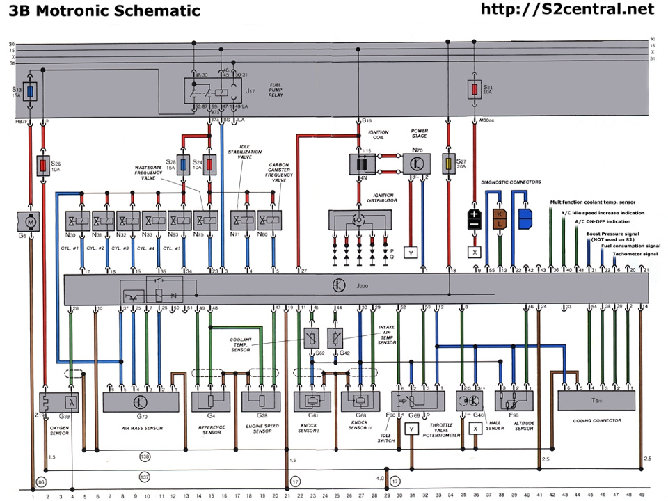
For the ABY and ADU, the connector is the same general configuration but the wiring is different:
The wiring listing for the ADU MAF connector is:
Position 1 = Brown/yellow to (138) ground (probably the intake manifold?)
Position 2 = Black/green from Pin T55/26 in the ADU ECU (looks like this one might be a white/green wire for an ABY)
Position 3 = Black/white from Pin T55/7 in the ADU ECU
Position 4 = Blue/violet from Pin T55/25 (holding relay) in the ADU ECU
Position 5 = Blue/black 12V power wire connected to the injector wire power circuit which is connected to Pin T55/37 in the ADU ECU (actually from the Holding Relay in the ECU)
Paul Nugent also said:
"The engine will not start if holding relay fails... it provides power to the chip that creates the +5V reference for MAF, Camshaft Position Sensor, etc - so even if the Fuel Pump Relay is energised when RPM is fast enough - there won't be supply voltage for MAF etc and there is no spark if Cam Sensor isn't energized. The easiest way to test if your holding relay is working - without removing anything... is turn the key ON and use a voltmeter at the white OBD plug on the 'K' wire. That should be approx 0.7V lower than actual battery voltage - if not then the holding relay is dead."
Recently (July 2013), another Holding Relay failure manifested itself, as posted on the S2Forum. The holding relay apparently failed closed, sending power to both Pin 4/6 and Pin 5/6 of the G70 MAF connector even with the engine off. While this was not an issue for Pin 5 (e.g. it left the injectors and MAF energized but the injectors would not do anything without a grounding signal from the ECU, as discussed in this injector wiring post). The big issue was the power to Pin 4/6 which comes from Pin T55/25 in the ECU (via the Holding Relay). This is the power to the hot wire that is intended to stay on for 5 seconds to burn off the crud on the hot wire when the engine is turned off. After the 5 seconds has passed there should be no power coming to the MAF via either Pins 4/6 or 5/6. If the power stays on, it continues to burn the wire (potentially shortening its service life), making the metal portion of the MAF skin-burnable hot and draining the battery. As a result, if you are having strange battery-flattening current draw, check for power at the injectors and/or the MAF at Pins 4 and 5.
REFERENCE: Holding Relay Importance:


Leave a comment:
-
Hmmm interesting, the first code i had when this all started was 4411, Injector 1 open or short circuit. But why would my Diagnostic ports all of a sudden stop working and my after run pump? Both which worked last week when the car was started last.
Electrical gremlins are a right pain to diagnose!! Just not my forte at all but will soldier on until the problem is found.
Leave a comment:
-
S28 is injectors + MAF. I would check the injector wiring harness, often crusty and in need of attention
Leave a comment:
-
Evening all,
The saga continues...
The new Hall sensor arrived from EFI safe and sound. Only took a few days from the states so delivery was spot on. Fitted it to the distributor this afternoon, made sure timing marks were all spot on etc then went for a start.
Engine spinning over with no signs of starting. Went to read codes with VCDS but not connecting to the module. Tried several attempts at connecting but with no joy. Checked the diagnostic fuse which was ok then sat down for a wee think. Turned the ignition on only to notice the after run pump for was not whirring away like it normally does for a few seconds,hmmm??
Started to check other fuses and came across fuse 28 blown which would be the Moteur fuse i think, had i not lost the wee red cover. Anyhow, what exactly does this fuse power? It keeps blowing fuses so gave up after a couple of attempts. Just done a quick search and i think it's just injectors, however i could be wrong. Been a long day looking after the wee ones so my head is done in.
My car is a 3B but running ABY ECU just for reference.
Any help much appreciated.
CheersLeave a comment:
-
-
I hope you find the issue soon as the difference in performance over chipped K24 is astonishing and worth the expense and work IMO.
Non the less everyone seems to experience some sort of issue when doing the pin swap mod from 80's tech 3B dissy to ABY coil on cylinder. Makes me want to leave mine alone on the dissy or go balls out and fit a complete RS2 engine loom, which I have the option of doing.
Anyway I hope you get it sorted sooner rather than later.
Leave a comment:
-
There is some interesting scope graphs on here which I think indicate that for the 3B the hall sender rotor window drops the voltage from @5V to @0V. This vehicle also had starting issues which were caused by a damaged crankshaft cam pulley.
Leave a comment:
-
Well I guess it depends on how the sensor is designed to work. Would need to see both on a scope to determine if they output the same or not. My gut feeling is the sensor itself is different and the reverse wiring is a red herring
Leave a comment:


Leave a comment: