No boost after engine/turbo upgrade

Collapse
X
 
  • Time
  • Show
Clear All
new posts

  • UrS4boy
    replied
    Originally posted by mike74
    Thanks for posting the link to my IAT post, Mike. Also available by clicking on the IAT label in the bottom right of this live engine bay device map:

    http://members.shaw.ca/ajmills/UrS%2...ice%20Map.html (a good one to book mark)

    Originally posted by K Simmonds
    I'm sure Dave will be along with specific info regarding the IAT sensor....
    Sorry to seem so slack guys but you're 8 hours ahead of me so my midnight beddies time is your 8 AM. Been a bit under the weather so I slept into 8:15 AM here (16:15 your time). Sorry.

    Anyway, I would have posted that link that Mike74 posted which contained the temp versus resistance graph.

    Note the substitution comment in my IAT post:


    034905379B *was* the AAN, ABY and ADU G42 IAT PN but it is NLA. I know that there was an earlier version on the 3B that was soldered into the harness directly (NO connector) but now the 3B listing is the same 034905379B but with a 443906232 two-pin flat contact housing.

    I am happy that I have a NIB spare for my AAN but I am concerned about others if their G42 start to fail.

    Leave a comment:


  • andy10v
    replied


    This sensor has a rubber boot to keep water/dirt out. On vehicles that have the sensor hard wired into the harness, if you want to measure the resistance of this air temp sensor, you must first isolate the sensor from the ECU circuitry.

    On the 1992-95 S4/S6, you can simply unplug the electrical connector at the sensor and measure the resistance directly across the air temp sensor terminals.

    On the 1991 200TQ 20V, you need to remove the ECU connector from the ECU. With the ECU connector removed, the resistance measured across the air temp sensor pins or across the appropriate ECU connector pins # 44 and # 2 to check the wiring between the ECU and the resistance of the sensor.

    You can also measure across terminals #44 and #30 as ECU terminals # 30 and # 2 are connected via a welded connection inside the ECU harness.

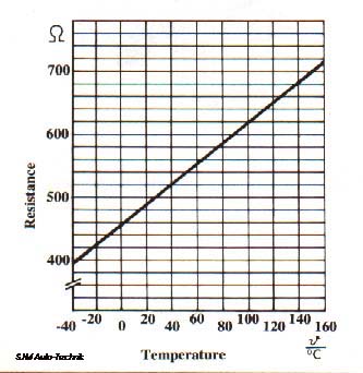
    The resistance should be approximately 500 ohms at 25C (70F). The resistance measured doesn't need to be "exactly" as shown, it just needs to be close to the value shown.

    Here is a graph of the sensor resistance versus temperature.

    Leave a comment:


  • gmac78
    replied
    Andy- Yeh good call with changing over to the ABY system, could do that no probs if i can source the correct bits and pieces. Or a 3B one could be soldered in i guess if one of them becomes available.

    Leave a comment:


  • gmac78
    replied
    Quick response lads, cheers. I've been observing the boost gauge when WOT is applied and you will see the gauge rise steadily to around 1.4- 1.5 bar, then there is a definite pause and a slight drop back by about 0.1-0.2 bar then a slow climb up to 1.6-1.7 bar. I think this is possibly where the timing/boost is getting pulled as you can feel and see it on the gauge.

    Like you say, logically it all makes perfect sense and will be quite happy if that is all it takes to finally let me sample the full fat RS2 power. It was quite late when i was tinkering last night so never checked resistance across the sensor as a secondary check, perhaps i can do that tonight before i head offshore tomorrow.

    Any other suggestions what i should try tonight with the limited time available?

    Thanks

    Leave a comment:


  • andy10v
    replied
    Glad you found an issue, I would imagine that would cause the ECU to hold back a bit!

    3B IAT sensor is attached to the loom.

    I would get an ABY IAT sensor, and an ABY connector, fit the ABY connector to the 3B loom and you can then just swap sensors without crimping or soldering in the future.

    Leave a comment:


  • K Simmonds
    replied
    That's all sounds logical, if your ECU thinks the inlet temp is that high then it's surely going to do something to try and keep the engine safe and have a serious effect on performance. The mid 30's is about right, 100 odd is way too high.

    What reading do you get in VCDS if you simply unplug the sensor? I wonder if you see 0 or a default value.

    I'm not sure if you can get the sensor new any longer or whether you'd be better off fitting an ABY one instead given that your now your using that ECU, regardless someone should have a good second hand one.

    I'm sure Dave will be along with specific info regarding the IAT sensor....

    Leave a comment:


  • mike74
    replied
    I'll get in before Dave does :
    The Audi Enthusiast website. Forums for all Audis including A4, S4, A5, S5, A6, S6, allroad, A8, S8, TT, R8, Q5, Q7, 4000, 100, 200, v6, v8, vintage, local forums

    Leave a comment:


  • gmac78
    replied
    Morning all,

    Not been near the car in the last few days but last night i managed to get a few hours.

    I think i've found the reason, or at at least i hope i've found the reason for the boosting issues. After coming back from a wee spin i checked measuring blocks on VCDS and my IAT was sitting at 103 degC. Wow!!!

    I let it cool down for a bit then took in out for another spin. With ignition on it shows -49degC and on start up jumped straight away to 70 degC. Out on the road it climbs quite quickly to 97-98 degC and settles there, the temp doesn't drop slightly as you would expect whilst coming on boost either.

    Once back from my second spin i checked the inlet manifold temp with a infra heat gun and it was showing 34 degC right beside the sensor, whilst the reading on VCDS was up at 97.7 degC or something.

    Whats your thoughts on this? Is this the root cause of my problem?

    If it is, can the sensor be calibrated or can a new one be purchased for a 3B?

    Thanks
    Gordon

    Leave a comment:


  • newsh
    replied
    No boost after engine/turbo upgrade

    Originally posted by UrS4boy
    Not sure about that one.

    I am, look closely you can read the numbers on it.

    Leave a comment:


  • UrS4boy
    replied
    G71 Manifold Absolute Pressure (MAP) sensor information

    Originally posted by newsh
    This is a 3Bar MAP
    Not sure about that one. I do know this is a 300 kPa = 3 Bar MAP sensor, ala RS2 ECU and chipped AANs and ABYs:


    This one too:

    http://www.efiexpress.com/catalog/pr...18419f06e962e1


    REFERENCE: G71 Manifold Absolute Pressure (MAP) sensor information:
    The Audi Enthusiast website. Forums for all Audis including A4, S4, A5, S5, A6, S6, allroad, A8, S8, TT, R8, Q5, Q7, 4000, 100, 200, v6, v8, vintage, local forums

    Leave a comment:


  • newsh
    replied
    This is a 3Bar MAP
    MPXH6300A

    Leave a comment:


  • newsh
    replied
    No boost after engine/turbo upgrade

    Originally posted by gmac78
    Evening all,

    I fitted what i believe to be a Motorola 3bar map sensor, it was new in a sealed wee tub but was so small i don't remember seeing any details on it. Is there any way to tell using VCDS etc if it is in fact a 3 bar sensor?

    The code numbers are on the side of the wee sensor, they are very small aren't they.
    It will have 300 written in small print. Anyway as long as you have the right one for the software you will be ok. If you have the wrong one you can get either too little or too much boost.

    I think the next place I'd look is the N75 and associated plumbing.

    The ECU controls boost by modulating the boost pressure applied to the wastegate lower chamber, if the N75 is sticking or won't open fully or the pipe to the MAF hose is blocked then you can get less than full boost.
    The N75 should be plumbed bottom leg of T to cold side, long arm to MAF hose, short arm the WG.

    It's always difficult to trace a problem with partly reduced boost, much easier if you're just seeing 0.5bar Spring pressure..

    Leave a comment:


  • UrS4boy
    replied
    Originally posted by newsh
    Faults can be cleared by removing the fuse for a matter of seconds, likewise adaptation is pretty much instantaneous and real time.
    Said "10 minutes" to make sure that there wasn't a capacitor still bleeding out.

    Leave a comment:


  • gmac78
    replied
    I'm using VCDS to clear the codes. I know when i would clear codes in my RS6 the fuel trim settings would also be reset. I assumed the S2 would be the same but possibly not?

    So far with the little use i have had out off car it's not quite the step in power i had imagined over the homefry. I'm still not getting the full 1.9 bar i should be with the V Stream chipset so perhaps once thats sorted it will improve things. Hopefully anyway!!

    Leave a comment:


  • newsh
    replied
    No boost after engine/turbo upgrade

    Faults can be cleared by removing the fuse for a matter of seconds, likewise adaptation is pretty much instantaneous and real time.
    Try in in Vagcom, make a fault by unplugging something while the engine is running. Pull the motor fuse(s) and replace quickly. Check vagcom again, no fault.

    Leave a comment:

Working...