You can change the style the forum displays by selecting your preferred style at the bottom left of the site.
We have made an enhancement so that old threads should now link from search results to the correct thread. This is not yet in place for single post links
Well I do mine up to 80nm anyway, since they come loose at the factory torque setting
I'm still to be convinced that friction alone will be enough to prevent them skewing with shock loads from 1ton of steel crashing over our third world road surfaces But if your calcs show otherwise then so be it
Panthero Coupé quattro 20vt
Indigo ABY coupé
Imola B6 S4 Avant
Did you have an idea set up in mind? I've just bought a beissbarth wheel alignment system and would be interested in doing some circuit testing with a car on slicks
Yummers, wheel alignment testing and corner weights! Your car is a rather extreme WAB so you could just cut and shut the strut tops inboard a little and the fronts rearwards aswell. These mounts are a bolt-on solution so is limited to what can be achieved within the standard parameters.
Wab, if you want to be tester no.2 then let me know, I need someone to buy another pair of mounts and test them. If you're after front and rear then even better.
I'll get this lot sorted and hopefully get testing next year.
When I fit them, I'll have a look at the dowel holes Alex, I might be lucky with myassembly solution fitting them
Cheers'en, AndyC
1994 ABY Coupe - Projekt Alpinweiss
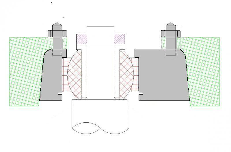
Here's a 2D scheme that I've knocked up. I'm struggling to find the pink metal, let me know if you have a supplier in mind.
All parts will be varnished so that they don't rust, especially the ally bits.
There are 3 screws holding in the bearing, I ditched the retaining ring as it was adding £30 to the cost of a pair and TBH was complete overkill. Other option was a circlip but space is really tight and there's no way of pre-loading the bearing and it's a tight fit anyway
Nice one trying to be constructive Re: cost and complexity:
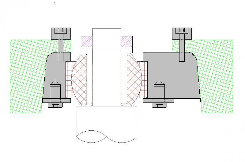
The top retaining ring / cover looks pretty elaborate? wouldn't a simple pineapple ring that bolts through to the mount body beneath a la 2Bennett be easiest and most effective? Or use studs with retaining nuts like 99% of "normal" pillowball type topmounts?
Is the conical bearer neccessary?
Can the bearing sit deeper inside the mount body to minimse raising the ride height? (an issue if running only front mounts i guess)
Must admit i much prefer the idea of a locking ring to retain the bearing rather than the 3 screws. Sure a circlip isn't possible?
Panthero Coupé quattro 20vt
Indigo ABY coupé
Imola B6 S4 Avant
Answering your questions (obviously you've just seen the design and I've been thinking about it for about a year now) -
I've carefully designed them so that there's minimal ride-height change Something between 3 and 4mm.
The top section is just a flat plate, the extra section that's not hatched is an optional cover that I'm working on. Can't get much simpler than a flat plate. The cover is just a finishing touch, I didn't explain that - my bad. This is not part of the stock mount.
There's no point having metal touching all areas when it's the upper face and boss that locate the top mount. The rubber gives a little and the metal would have to exactly match the contours to ensure a proper fit. A no-go IMO. The grey sections that you have put in are not required unless you're going for a poly mount to try and allow for some movement and thus reduce NVH. The boss and top section locate the bush an transfer the load respectively.
The design allows for the addition of a lock ring but TBH it does nothing more than 3 screws and washers (other than add cost), hence why I removed it. The bearing does not get pulled down by anything other than the weight of the strut as the spring is pre-loaded to push up... It would only be held in place by the same number of retianers anyway and thin ally wouldb offer anything that a washer doesn't. It only does anything when the car is in the air and then there's plenty of retaining force there to hold the strut. I could put in a retaining circlip but they won't push the bearing into the housing so will clunk a little when loading and unloading - not ideal. Bolts are a better solution IMO, hence why I've gone that way.
The taper on the body ensures that there is a bit of meat to get the screws underneath into, it also give a nice wall section of aluminim on the narrower side, if you go straight down then either there's not enough wall section or the top face will interfere with the radius of the strut housing, either way, a taper is best and I've gone for a 15deg taper on two places to remove tool change.
The two designs you show involve drilling the strut top so are not a bolt on solution. If Audi was sensible like many other manufacturers then there would already be holes there but the small strut leaves little place to mount it and there's too much margin for error, a strut top is hardly a simple piece to replace if someone got it wrong or it cracked due to the hole weakening the structure.
Here is what I did when I mad mine ,the photos are not the finished product but just some I knocked up when sizing it up , what you see is basicly what I have in testing on the car the only difference is .5 mm here and there and the final one has a circlip groove to hold the bearing in place as the one in the photos dose not have this .
The top nut also has a nylon lock ring in it so it cant come loose .
I used a taper also but over that goes a polypropylene expanding collet .
The centre bearing housing when tightened in to the polypropylene outer expands the outer of the polypropylene sleeve collet by 1 mm thus squashing it very tightly into the cup in the wing .
I wanted to make sure the load form the housing was transferred into the radius of the cup in the wing as this is the way the standard mount works .
I chose polypropylene as I did not want it to have any give in it but I could of used polyurethane as the thickness of the collet it is unlikely there would be ant give in it. Th e other advantage of this disgn is that it will not shuffle around and wear its way through the paint/rust protection .
The problem with a lot of designs is that they don't locate in the way that Audi intended , they locate through the hole and the force is transferred through the flat inside the the cup and not the radius . The problem with this is that it allows twisting of the steel in the top of the cup .
I have seen a car that was used on the track that had this type of mount that had worked hardened the steel in the top of the cup and the mount had broke through , it was then held in place by the bonnet !
If anybody wants to use this design , the expanding taper collet then feel free I won't be offended , as far as I know no one else has taken this approach to the location of a strut top mount.
I used to like making all kinds of stuff for cars at work but were I work currently it is so busy that I can't get use of the machines often enough even to to stuff just for me .
there was I time a wile back after the recession when it was quiet and I decided to do a few things but china has kicked off again and we are mad busy as most of are stuff goes to them .
fair play, thats a really good idea
I think you are definately right i.e. the shape of the mount needing to fill the turret top as per the oe mounts.
Thanks , though people would like it.
I was originally going to offer to make them for people but as I said above I just cant get the machine time now and it would cost too much for me to have someone make them so if anyone wants to copy the idea feel free .
A neat solution indeed. Problem is, if you cost up all of those parts then the cost goes up and up, I could have a poly section made up to sit the mount on but it would add £20-£30 / side to the cost... they're already more expensive than I'd like... I bet the design shown above are heading towards £250 a pair cost price, if it wasn't just your time and some scrap(?) material then that would translate to £400 + a pair of bearings.
As I say, to redesign the mount to use a poly upper section would add to the already high cost. I can replicate the shape of the OE mounts but the problem here is that I don't know the shape of the cup, only the bush - if there is some designed in flex in the system then it'll mean that the body won't fit properly... By making sure there's clearance, there's not the possibility of the mount sitting badly. Also, the curve isn't tangential, it's made up of several radii blended together.
These are as wide as I dare go on the OD so spread the load nicely - again, I've measured the OE bush and gone as wide as the non-curved part allows (63mm), after this and they curve away, to go any wider would involve some possible high spots and way more than the 4MPa pressure that this design exerts on the front strut tops!
Some mounts might be narrower (because they use smaller bearings and want to reduce material costs) and so the pressure on the strut top will be higher, this would explain what you saw. One option is to take some material off the inner section to move the load path outboard and away from the centre hole, however, this increases the pressure on the load bearing part. The material is 6mm steel on the S2 (4mm strut, 2mm from the strut brace) and so is well up to the job. My design then also adds a 1/4" ally top plate to stregthen up the entire top plate, nit just some of it.
I've used 4 off M8 bolts to hold the top cap to the body, that could be more than enough clamping force over the 70mm OD top plate to give plenty of friction and prevent movement.
Don't forget, any flex in a material used to insulate the body has to be allowed for in the upper segment to prevent the friction being lost on the top plate as it is lifted off the strut. As such, any flexible material used on the body needs to be used between the strut top and top plate. This material then needs to be carefully pre-loaded to ensure that it does not come loose when under maximum load. To do so could cause shock loading and the geometry to be lost when it all settles - this is for offset bushes, not concentric.
Cheers'en, AndyC
1994 ABY Coupe - Projekt Alpinweiss
One thing I'll look into is replicating the taper, by ignoring the complex curve of the transition from top face to taper, I can get something with a good approximation of the OE taper.
Cheers'en, AndyC
1994 ABY Coupe - Projekt Alpinweiss
We process personal data about users of our site, through the use of cookies and other technologies, to deliver our services, personalize advertising, and to analyze site activity. We may share certain information about our users with our advertising and analytics partners. For additional details, refer to our Privacy Policy.
By clicking "I AGREE" below, you agree to our Privacy Policy and our personal data processing and cookie practices as described therein. You also acknowledge that this forum may be hosted outside your country and you consent to the collection, storage, and processing of your data in the country where this forum is hosted.

 Tweet
Tweet

 But if your calcs show otherwise then so be it


 By making sure there's clearance, there's not the possibility of the mount sitting badly. Also, the curve isn't tangential, it's made up of several radii blended together.
Comment