From Audi 100 to urS4 in a week

Collapse
X
 
  • Time
  • Show
Clear All
new posts

  • UrS4boy
    replied
    Originally posted by hunker7
    Thanks for the info. That could be very helpful, thanks.
    Or NOT:

    from a previous post of mine on qW:

    "Based on Bentley X62 for UrS4 and page W90-25

    Colour...Function

    Black.....Analogue Clock Adjustment
    Brown....(+) Terminal 30 - to instrument cluster dimmer switch
    Red.......(+) to Voltage stabilizer J166
    Orange...(+) to Voltage stabilizer and then cluster bulbs
    Yellow....(-) Ground
    Green....(+) Power to Oil Temp and Pressure Gauges

    But please take the above with a large grain of salt, and check for yourself."

    In retrospect, what I don't see there is the signals from the UrS4 oil pressure and temp senders. Needs more investigation.

    Leave a comment:


  • hunker7
    replied
    Originally posted by UrS4boy
    10 = 4A0919059M = printed circuit for models with revolution counter, check package and/or on-board computer. S4, S4 4.2L
    11 = 4A1919060 = printed circuit for additional instruments
    16 = 4A1919078 = base plate for clock, oil temperature gauge and oil pressure gauge

    Been thinking, I think I might have the pin-outs for the rainbow ribboncable between the main board and the instrument cluster board. That *might* help you (or not). IF I can find it.

    Thanks for the info That could be very helpful, thanks

    Leave a comment:


  • UrS4boy
    replied
    Originally posted by hunker7
    I did but isn't part 11 the board for them 3 gauges and part 10 for rest of the instrument cluster?
    10 = 4A0919059M = printed circuit for models with revolution counter, check package and/or on-board computer. S4, S4 4.2L
    11 = 4A1919060 = printed circuit for additional instruments
    16 = 4A1919078 = base plate for clock, oil temperature gauge and oil pressure gauge

    Been thinking, I think I might have the pin-outs for the rainbow ribboncable between the main board and the instrument cluster board. That *might* help you (or not). IF I can find it.

    Leave a comment:


  • hunker7
    replied
    I did but isn't part 11 the board for them 3 gauges and part 10 for rest of the instrument cluster?

    Leave a comment:


  • UrS4boy
    replied
    Originally posted by hunker7
    Ah understand. I thought those 3 gauges would be separate to rest of the speedo.


    Did you even look at post 764?

    And please try not to call the *instrument cluster* the "speedo". Speedos are brand of swimming trunks and speedometers are just one component of the instrument cluster.

    Leave a comment:


  • hunker7
    replied
    Originally posted by UrS4boy
    You are missing the key point: *EVEN IF* you could find some aftermarket, white/grey-faced, true back-lit gauges, you would still have to figure out the OE circuit board and then patch in wiring to those gauges. Not impossible but not a doddle either.
    Ah understand. I thought those 3 gauges would be separate to rest of the speedo.

    Leave a comment:


  • UrS4boy
    replied
    Originally posted by hunker7
    It's definitely beyond my skill. What I meant was, I could replace all 3 gauges with aftermarket ones. ... but you get the idea.
    You are missing the key point: *EVEN IF* you could find some aftermarket, white/grey-faced, true back-lit gauges, you would still have to figure out the OE circuit board and then patch in wiring to those gauges. Not impossible but not a doddle either.

    Leave a comment:


  • hunker7
    replied
    should be easy I just think it messes the looks up

    Leave a comment:


  • Dift
    replied
    Looks like I'm probably going fast and furious with my boost guage

    Might have a try with the centre vent. Shouldn't be too difficult.

    Leave a comment:


  • hunker7
    replied
    It's definitely beyond my skill What I meant was, I could replace all 3 gauges with aftermarket ones. For instance:
    http://www.ebay.co.uk/itm/2-52mm-LED...item5d47002e8f

    Not these ones as they look horrible, but you get the idea.

    Leave a comment:


  • UrS4boy
    replied
    Originally posted by hunker7
    Personally not a fan of vent/pillar gauges, so I like that idea.
    It's a good idea. Just very likely beyond your skill level. In almost 17 years of UrS ownership and UrS forums, I have only seen 2 boost gauges installed where the clock was. Nobody ever shared how exactly then did it either. (Nice, thanks guys).

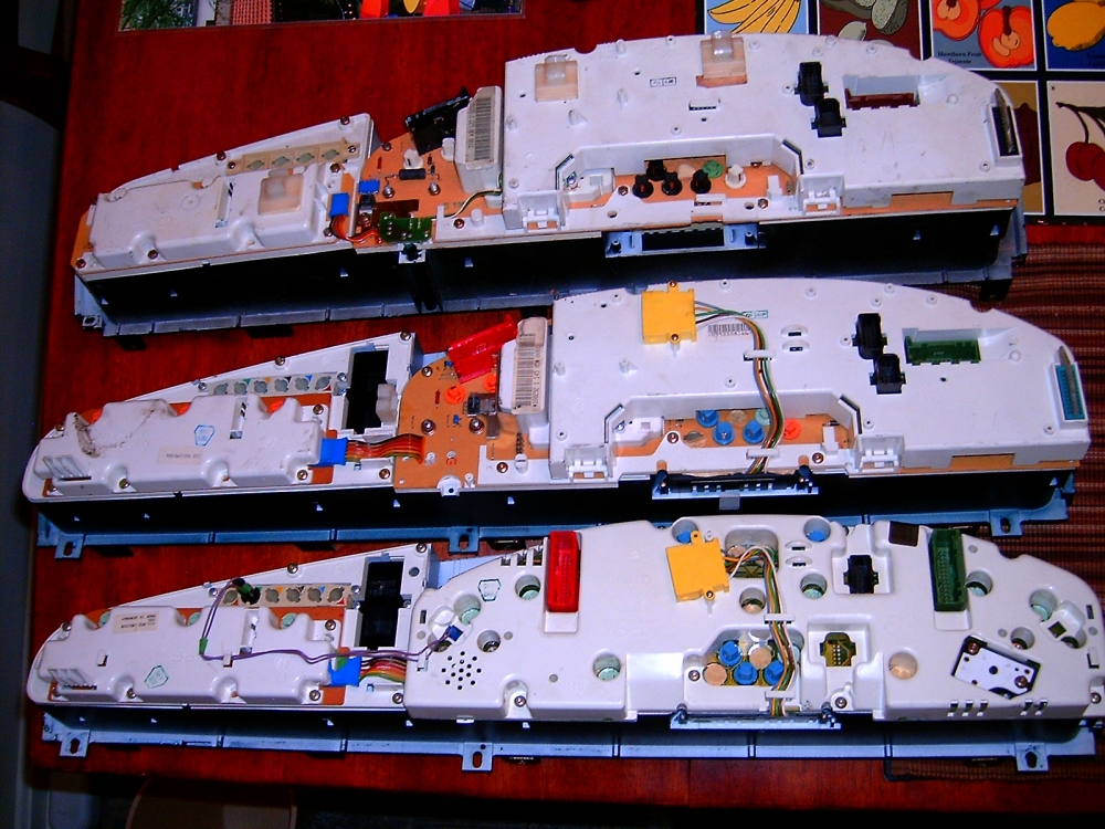
    To do it, you'd have to a) figure everything out about Item 16, printed circuit board and b) the re-engineer connections/wiring to individual gauges. Maybe you could do it. But even then, the location is NOT optimal for checking while driving. A-pillar or steering column pod would be better. I mocked up something for the top of the dash but didn't get any support/demand so I dropped it. (I am more than happy with my A-pillar gauge pod)(See below)


    Back side of Audi 200, UrS4 and UrS6 clusters:


    Leave a comment:


  • hunker7
    replied
    Originally posted by UrS4boy
    Good luck with that.

    (Way too much work for really very little gain, if any)

    But hey.
    Personally not a fan of vent/pillar gauges, so I like that idea.

    Leave a comment:


  • UrS4boy
    replied
    Originally posted by hunker7
    Another way is to replace all 3 gauges with same style ones
    Good luck with that.

    (Way too much work for really very little gain, if any)

    But hey.

    Leave a comment:


  • UrS4boy
    replied
    Originally posted by Dift
    Are digital or analogue gauges best?
    Digital, including the OE in-dash gauge, are too slow. You want an analogue gauge that goes from 30 inches of Hg (mercury) vacuum to 30 psig (relative) boost. (Or say 750 mm Hg vacuum to 2 Bar boost).

    Leave a comment:


  • Dift
    replied
    182k good effort! A few more miles than mine.

    Are digital or analogue gauges best?

    Hoping to buy one this weekend in some shape or form.

    Leave a comment:

Working...