Announcement

Collapse
No announcement yet.

Audi Coupe OEM+ Interior Lighting Guide

Collapse
This is a sticky topic.
X
X
 
  • Filter
  • Time
  • Show
Clear All
new posts

  • I had the front off my S2 headlamp level switch the other as I had a theory about Audi changing from bulbs to LED's on all the switches late on.

    The run-through earlier on for the headlamp range control, used the switch from my 1993 TDi.
    I wondered if there'd be a difference between that and the one in the S2.
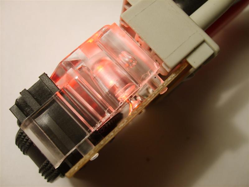
    Was right too, the red plastic light diffuser is clear in the S2's switch. That means it either uses a red bulb or a clear LED that shines red like the big seat heater switch in the last run-through.
    Strangely, saw one on ebay, brand new in the box for less than a new one at a dealers, so thought I'd nab it >> Ebaylinky

    Arrived today.
    Same part number as the one in the TDi, but as said it's subtly different inside and looks to be the same as the one in my S2.
    8A0 941 301 is the number.
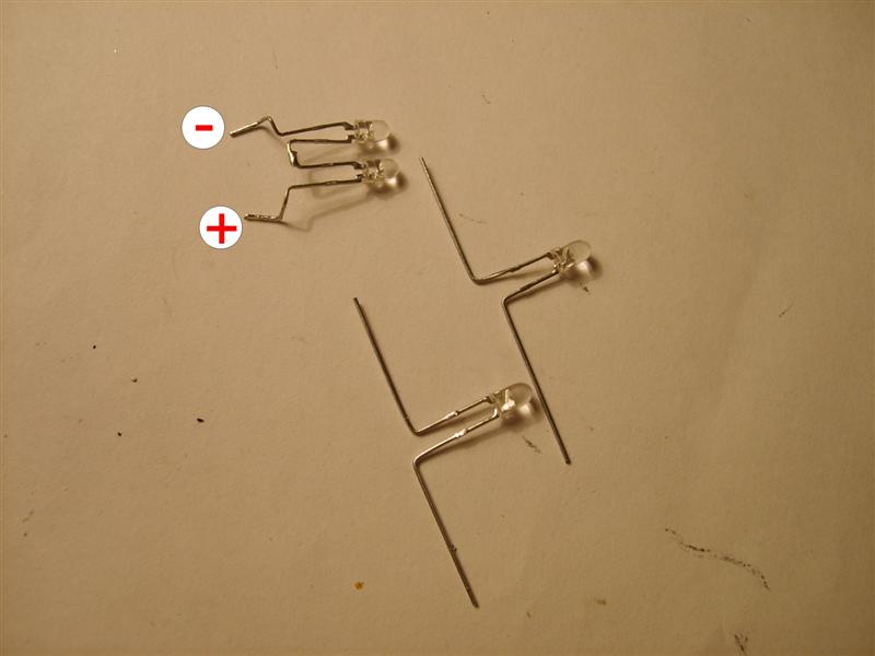
    Same process would be needed to change the illumination source as posted further back. You'd just need either a red bulb (number from Maplins given further back) or another 12v clear LED that shines red.

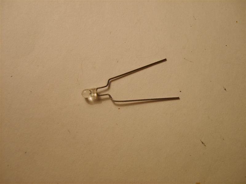
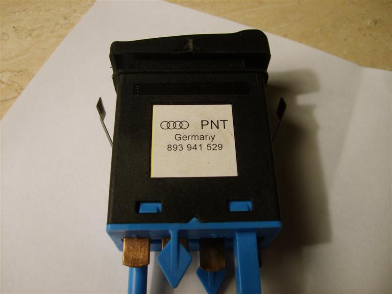
    Here's some pictures of the later headlamp level switch with it's different illumination source for the archives;

    A recap first, the earlier one from my 1993 b4 80 TDi (same part number)


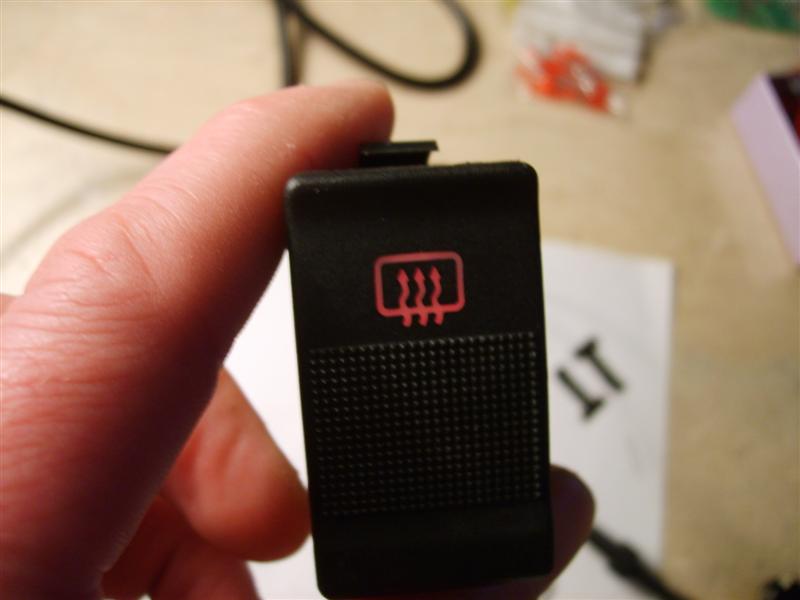
    AND the later updated one (again, same part number)


    Last edited by Jas11n; 2 December 2008, 22:53.
    2001 Avus Silver B5 RS4.
    2004 A4 Avant 1.8T quattro Sport-LE.
    1995 S2 Coupe - sold (sniff)

    Comment


    • Interesting, if its clear it could be made to light up blue.

      Last edited by newsh; 2 December 2008, 22:54.

      S2 Coupe 3B Project


      Ur quattro restoration

      S2 Avant

      Boost is the new rock and roll!
      sigpic

      Comment


      • Next up, a later heated rear window switch that uses LED's instead of the earlier easily replaceable 5mm wedge bulbs.
        This switch belongs to Martinjs from his urS4, but it's the same as those fitted to the S2's. It's the usual press in, stays in, press in and it comes out again, type switch (sorry, that a crap explanation)
        (The heated rear window switch in my S2 is slightly different again, it's a momentary 10-minute timed switch.)

        The faceplate on most of the dash switches will just easily lever off, but some, like this one require the switch to be removed before you can take the front off. You need to press down the tabs on the top and bottom first. (If you are confident LED's reside inside, then you don't really need to remove the front, just skip that bit and take the innards out)


        Remove the inner board in the same as other switches, lift up the outer casing over the four tangs (two each side) on the inner casing and slide it out from the rear


        This is what you'll be faced with. The top 3mm LED is for the heated rear screen image illumination, the bottom two clear LED's that light up amber/yellow are for illuminating the amber/yellow triangle when the switch is on


        As with all LED's, you need to know which is negative and positive. Take note of the image below. (On the rear, earth terminal is number two, positive connection for image illumination is number one, positive connection for triangle illumination is number five)


        Martin's switch had lost the amber/yellow illumination LED's, but also I noticed the red LED for the image illumination was very dull, so I decided to replace that too.
        The two clear LED's are joined together in the centre, so it's just a case of de-soldering either end and listing it out from the top. Again, you'll need a de-solder pump to effectively remove excess solder. They are soldered to the top of the PCB, but the legs do protrude down through the board, so make a note of how far on the old set for later so you don't have them protruding through too far.
        Here's what they look like once out


        Now you'll need two replacement LED's.
        As I've now sourced a local supplier of various bulbs and LED's, I can't link to a supplier. As you'll see above, the PCB contains resistors, so your replacement LED's need to be rated for around 3v, if you use an LED rated for 12v in conjunction with said resistors, you are going to dim it. So look for 3mm 3v versions instead. They don't necessarily have to be colour shining clear versions, coloured LED's will do just as well.
        I do have some 3mm 3v yellow shining clear versions, so I used them. You need to copy the way the original set is configured. Remember to take note of the polarity configuration, you are joining the earth (short leg) of one LED to the positive (long leg) of the other.


        Once you have got the centre legs soldered together and the legs bent into the right shape, insert it down into it's holder before soldering and check with a 12v power source to make sure it lights up ok. If all is ok, solder it in place


        2001 Avus Silver B5 RS4.
        2004 A4 Avant 1.8T quattro Sport-LE.
        1995 S2 Coupe - sold (sniff)

        Comment


        • With that done, I moved on to the red LED that illuminates the image on the faceplate. It a bit of a sod to get out, I just snipped the whole LED off both legs, then individually removed each leg.


          I have loads of the superbright 3mm 12v LED's (cj70m's) like I used in the window switch, but again, this board has resistors so I used a 3mm 3v red shining clear LED instead. Was a good move replacing it, as the original was very dull. Again, the legs were bent and trimmed to fit like the old one and then checked before soldering it up


          (Note, the two earlier LED's look all out of line in the below picture, they weren't fully fitted and soldered in at this stage)


          All now sorted and soldered in


          Reverse removal to get everything back together and recheck with a 12v power source.


          Oh, one last thing, I thought the way in which the PCB had been soldered when it was manufactured was very sloppy, so took a bit of time to remove all the excess brown flux that had been left all over the PCB. No reason other than to tidy it up.

          2001 Avus Silver B5 RS4.
          2004 A4 Avant 1.8T quattro Sport-LE.
          1995 S2 Coupe - sold (sniff)

          Comment


          • On that note, all the switches in my 96 cab are LED based, just like the rear window switch you've shown above. Headlight level switch was just like you said too, with a red LED and transparent light-guide-thing (if thats a suitable name for it).

            Just for useless info too, the empty space under the two amber LEDs is used in the foglight switch for a red LED for the factory alarm, so there is a total of 4 LEDs in that switch! Fun times - I must have something better to do than take my switches apart...

            Obviously I don't!

            Comment


            • Thanks again Jas,
              How did those cig lighter bulbs come out?
              Anyone know the reason why there are few different versions of the same switch? which essentially all do exactly the same thing.

              Comment


              • Originally posted by maddagent View Post
                On that note, all the switches in my 96 cab are LED based,
                Yup, all the ones in my S2 dash are LED based too.

                I guess they changed them later to LED's to be more longer lasting, than the earlier versions using the 5mm wedge bulbs.

                Originally posted by martinjs View Post
                Thanks again Jas,
                How did those cig lighter bulbs come out?
                Had to break the legs off each bulb. I thought they'd be soldered in, but they aren't. Each leg is resistance welded to it's terminal. It's a form of spot welding really. I used to work for an electronics company a few years back and one of it's products (RFI filter) used to have a copper earth strip spot welded to an aluminium case. A fine art, but possible. The wire leg of the bulb is pressed hard against the terminal and a current run through it, resistance causes heat and the wire is spotted to the terminal.
                It's the same system they used to attach the LED and resistor to the terminals inside the window switch.

                When I put the new ones in, one could be soldered easy enough with normal solder, it flowed and soldered easy enough. The other I had to use some acid flux solder instead, which flows faster and allows you to solder to metal normal solder won't attach to.

                (Note, this is a bulb and holder from a urS4's cig lighter. They are a separate item which Audi want you to purchase if the bulb blows. The urS4 has two cig lighters, one in the rear and one in the front. The bulb in the one cig lighter of S2's/RS2's etc are easily replaceable with 5mm wedge bulbs)

                I had to use one of the long wired bulbs rather than using the original 5mm wedge size, as the legs were not long enough for me to get them to an area to solder without the soldering iron melting the plastic holder and messing it up.
                As the thing is so small, I had bother taking pictures, but here's some anyway.

                Remains of the old bulbs leg on the right of the steel terminal. It's not soldered but spot welded;


                Bulb used with longer legs, as I couldn't solder in the original place further up due to not wanting to damage the plastic holder;


                Acid flux solder used to attach leg to the steel terminal;


                New bulb lit up. It's physically smaller in size than the original, but at 1w is only .1 down on the other. Not enough to notice a difference.


                It's a tiny little bùgger;


                PS, doesn't the queen look a grumpy old coot on that penny
                Last edited by Jas11n; 7 December 2008, 14:07. Reason: spelling DOH
                2001 Avus Silver B5 RS4.
                2004 A4 Avant 1.8T quattro Sport-LE.
                1995 S2 Coupe - sold (sniff)

                Comment


                • Received this last week, interior light switch that Skull mentioned way back near the beginning of the thread. Still available to buy new, was only £13 but you'll need the multiplug connector for the rear and the wiring with pins which bumped the price up a bit.
                  Just need to study the schematics for the interior lights and I'll need a relay for it to work properly. Also bought the two way radio button too (waiting for it to arrive), has "FUNK" on the front of it. Got a plan for that one


                  2001 Avus Silver B5 RS4.
                  2004 A4 Avant 1.8T quattro Sport-LE.
                  1995 S2 Coupe - sold (sniff)

                  Comment


                  • I connected it the easy way, it is only switching the ground on of to all the interior lights. this way, the green light does not turn on. i knew that sooner or later i will have someone that will do the study for me
                    Audi Quattro WR

                    Comment


                    • jase,are you going to have enough room for all these switches??? hehe

                      Comment


                      • Originally posted by A80Avant View Post
                        jase,are you going to have enough room for all these switches??? hehe
                        I currently have two blanks, so there's enough

                        Originally posted by Skull23 View Post
                        I connected it the easy way, it is only switching the ground on of to all the interior lights. this way, the green light does not turn on. i knew that sooner or later i will have someone that will do the study for me
                        I think what I'll do is tie it into a door contact switch.
                        When the door is closed, the switch is closed and the earth circuit is complete, open the door and the switch opens, breaks the earth circuit and the lights all come on.
                        On a normal four pin relay, the circuit would be open until you activated whatever it was connected to, it'd then close and the circuit would be complete. I want the reverse of this.
                        I'll use a five pin relay, so that I can use pin 87a and have the circuit always closed until it's activated where it will then go open circuit, so it'll emulate the door contact switch. This way I don't mess with any of the live circuits in the system as they are connected to the CL pump and alarm.

                        2001 Avus Silver B5 RS4.
                        2004 A4 Avant 1.8T quattro Sport-LE.
                        1995 S2 Coupe - sold (sniff)

                        Comment


                        • maybe you are complicating this too much. a normal 4 pin relay would be enough i think. What you need it a permament 12v, that goes into the button, when pressed, the light comes on, and connects 85 and 86, that switches the ground on 30 and 87, one of which goes to the interior lights ground.

                          the taxi button must be working regardless of the doors open/closed, ignition on/off etc...
                          Audi Quattro WR

                          Comment


                          • Yes, but if you tap into the actual ground wire of the circuit (not the door switch ground) wouldn't that mean a cut in the grounding until you pressed the switch, making the system inoperable at all other times? Although saying that, if I read your post above, that's how you have it now, only without a relay
                            You are right, I'll probably use a permanent 12v to pin 5 on the push switch, that way it works regardless of whether the ignition is on or off.
                            I'll keep it a switched 12v on pin 1 so that the switch image illumination comes on like the rest. I'll probably tap a feed from a switch next to it.

                            Hopefully (weather permitting) I'll be having a go at this on Friday.
                            2001 Avus Silver B5 RS4.
                            2004 A4 Avant 1.8T quattro Sport-LE.
                            1995 S2 Coupe - sold (sniff)

                            Comment


                            • you basically need 2 grounds, one for the relay to work, the other for the actual ground for the lights, hmmm, and the third for the button lights to work...

                              having 2 grounds connected at the same time (dor open and swith pressed in) does nothing bad, you only have a better ground, and if you close the door, the lights are still on, as the switch is in. that is why playing with grounds is easy, you cant fire anything.
                              Audi Quattro WR

                              Comment


                              • I love this thread.

                                Going to order the "Taxi" switch to trigger my five interior lights in my Avant, not including the boot one.

                                Going to order the "Funk" switch to use as an on / off switch for my red Becker radio.

                                Being lazy, Jas11n can you indulge me and advise what colour the wire is in the factory loom and where in the factory loom do you recommend to tap into it to make use of the speed / volume facility of the Becker?

                                Secondly, earlier in this thread as you so helpfully gave the Maplins ref numbers for the various switch's LED / bulbs, can you recommend a HID style light colour LED bulb to replace the standard bullet shaped bulbs in the interior lights? I know it may have been covered elsewhere, but this is turning into one hell of a sticky, at this stage?

                                I'm sure others, also keeping a watching eye on this thread, would be glad of your experience in relation to this second query.

                                One last point, can you advise what terminals on the back of the switches does one use to check if the new LED / bulb is working before putting them back into the car? This query also applies to the mirror and window switches in the driver's door handle.

                                Thanks either way.

                                Kind regards.
                                Last edited by macspring; 10 December 2008, 02:14.

                                Comment

                                Working...
                                X